


3-70 ENGINE
ENGINE REASSEMBLY
•Reassemble the engine in the reverse order of disassembly.
•The following steps require special attention or precautionary measures should be taken.
NOTE:
Apply engine oil to each running and sliding part before reassembling.
• Be sure to install the following items to the crankcase.
*Crankshaft journal bearings ( 3-67)
*Driveshaft ( 3-56)
*Gearshift fork shafts ( 3-43)
*Gearshift shaft bearings ( 3-55)
*Gearshift cam bearings ( 3-55)
*Gearshift cam ( 3-56)
*Driveshaft bearings ( 3-56)
*Oil jets ( 3-58)
PISTON RING |
|
|
|
|
E |
|||
• Install the piston rings in the order of oil ring, 2nd ring and 1st |
|
|||||||
L |
||||||||
ring. |
|
|
|
|||||
|
|
|
|
|
|
|
||
• The first member to go into the oil ring groove is a spacer 1. |
|
|
|
|
||||
After placing the spacer, fit the two side rails 2. |
P |
|||||||
|
|
|
|
|
|
|||
NOTE: |
M |
|
|
|
|
|||
|
|
|
|
|
||||
Side designations, top and bottom, are not applied to the spacer |
|
|
|
|
||||
|
A |
|
|
|
|
|
|
|
and side rails: you can position each either way. |
|
|
|
|
|
|
||
|
S |
|
|
|
|
|
|
|
|
|
|
|
|
|
|||
|
|
|
|
|
|
|
||
|
|
|
|
|
|
|||
When installing the spacer, be careful not to allow its |
|
|
|
|
||||
two ends to overlap in the groove.
A INCORRECT
BCORRECT
•Install the 2nd ring 3 and the 1st ring 4 to the piston.
NOTE:
1st ring and 2nd ring differ in shape.

ENGINE 3-71
•1st ring 4 and 2nd ring 3 have letters “IT” and “T” marked on one side. Be sure to bring the marked side upward when fit-
ting them to the piston.
• Position the gaps of the three ring as shown. Before inserting |
|
|
EX |
|||
each piston into the cylinder, check that the gaps are so |
|
|
|
|||
located. |
|
|
|
|
|
120 ¡ |
|
|
|
|
|
120 ¡ |
120 ¡ |
|
C 2nd ring and lower side rail |
|
|
|
||
|
D Upper side rail |
|
E |
IN |
||
|
E 1st ring and spacer |
|
||||
|
|
|
||||
|
|
|
|
|||
|
|
|
|
|
|
|
PISTON AND CONROD |
|
L |
|
|||
|
|
|
|
|
||
• Apply a small quantity of MOLYBDENUM OIL SOLUTION |
|
|
|
|||
onto each piston pin. |
M |
|
|
|
||
MOLYBDENUM OIL SOLUTION |
|
|
|
|||
|
P |
|
|
|
||
• Assemble the piston and conrod. |
|
|
|
|
|
|
NOTE: |
A |
|
|
|
|
|
|
|
|
|
|
|
|
When installing the pistons, the indent on the piston head |
|
|
|
|||
must be brought to the other side of ID code |
B on the conrod |
|
|
|
||
big end. |
S |
|
|
|
|
|
• Install the piston pin circlips 1.
Use new piston pin circlips to prevent circlip failure which will occur with a bend one.
NOTE:
End gap of the circlip should not be aligned with the cutaway in the piston pin bore.
•Apply a small quantity of MOLYBDENUM OIL SOLUTION to the sliding surface of the pistons and cylinder walls.
MOLYBDENUM OIL SOLUTION
NOTE:
Be sure to install the pistons in the cylinders from which they were removed in disassembly, referring to the cylinder numbers, “1” through “4”, scribed on the piston.

3-72 ENGINE
• Install the pistons and conrods into the cylinders from upside.
NOTE:
When installing the pistons, the indent C of each piston head must be brought to the exhaust side.
Be careful not to damage the cylinder wall and piston jet by the conrod.
|
|
|
E |
• Check that I.D. code D on each conrod faces intake side. |
L |
||
|
|
P |
|
|
|
|
|
|
|
|
|
Be sure to clean the conrod big end. |
|
|
|
|
|
|
|
|
|
M |
|
|
A |
|
|
|
S |
|
|
•Apply a MOLYBDENUM OIL SOLUTION to each crank pin bearing surface and crankshaft journal bearing surface.
MOLYBDENUM OIL SOLUTION
CRANKSHAFT
•Position the No. 2 and No. 3 conrod big ends on the same side, and the No. 1 and No. 4 conrod big ends on the opposite side of No. 2 and No. 3.

ENGINE 3-73
• Set the crankshaft to the conrods and upper crankcase.
• Apply engine oil to the crank pin and bearing surface.
Be sure to clean the conrod big end.
• When fitting the conrod cap, make sure that I.D. code A on each conrod faces intake side.
|
|
|
|
|
E |
• Apply engine oil to the bearing cap bolts. |
|
L |
|||
|
|
|
|||
• Tighten the conrod bearing cap bolt by using a 10 mm, 12 |
|
||||
point socket wrench in the following two steps. |
P |
|
|||
Conrod bearing cap bolt: |
|
|
|||
Initial : 15 N·m (1.5 kgf-m, 11.0 lb-ft) |
|
|
|
||
|
A |
|
|
|
|
Final : 90° (1/4 turn) |
|
M |
|
|
|
S |
|
|
|
|
|
• Apply engine oil to the conrod big end side surfaces. |
|
|
|||
• Check the conrod movement for smooth turning.
90˚
•Apply a MOLYBDENUM OIL SOLUTION to each crankshaft journal and bearing lightly.
MOLYBDENUM OIL SOLUTION

3-74 ENGINE
•Insert the right and left thrust bearings with oil groove B facing the crank web.
NOTE:
Right thrust bearing has green painting.
COUNTERSHAFT
•Install the C-ring 1 and bearing pin 2 to the upper crankcase.
|
|
E |
• Install the countershaft assembly to the upper crankcase. |
L |
|
|
||
NOTE: |
|
|
Align the C-ring with the groove of bearing and the bearing pin |
|
|
|
M |
|
with the indent on the bearing. |
P |
|
|
A |
|
S |
|
|
• Turn the bearing to fit the bearing dowel pin in the position A.
•Install the dowel pin and oil seal 3.
•Install the gearshift shaft and fork 4, bushing 5 and retainer
6.

ENGINE 3-75
CRANKCASE
• Clean the mating surfaces of the crankcases.
• Install the dowel pins.
• Install the dowel pins, O-ring 1 and cap 2.
Replace the O-ring with a new one.
•Apply SUZUKI BOND to the mating surface of the lower crankcase.
99000-31110: SUZUKI BOND “1215”
|
(or equivalent bond) |
|
|
|
|
|
NOTE: |
|
|
|
|
|
|
Use of SUZUKI BOND is as follows: |
|
|
|
|
|
|
* Make surfaces free from moisture, oil, dust and other foreign |
|
|
|
|
|
|
materials. |
|
E |
|
|
||
* Spread on surfaces thinly to form an even layer, and assemble |
|
|
||||
the crankcases within few minutes. |
L |
|
|
|||
|
|
|
|
|
|
|
* Take extreme care not to apply any bond to the oil hole, oil |
|
|
|
|
|
|
groove and bearing. |
|
|
|
|
|
|
* Apply to distorted surfaces as it forms a comparatively thick |
|
|
|
|
|
|
film. |
M |
|
|
|
|
|
P |
|
|
|
|
|
|
A |
|
|
|
|
|
|
S |
|
|
|
|
|
|
|
|
|
|
|
|
|
|
|
|
|
|
|
|
|
|
|
|
|
|
|

3-76 ENGINE
• Tighten the crankshaft journal bolts (M9) in ascending order |
|
|
|
|
|
||||
of numbers assigned to these bolts. Tighten each bolt a little |
|
|
|
|
|
||||
at a time to equalize the pressure in the following two steps. |
|
|
|
|
|
||||
Crankshaft journal bolt: (M9) |
|
|
|
|
10 |
6 |
2 |
4 |
8 |
|
|
|
|
|
|
|
|
|
|
Initial : 18 N·m (1.8 kgf-m, 13.0 lb-ft) |
|
|
9 |
5 |
1 |
3 |
7 |
||
Final : 50° |
|
|
|
|
|||||
|
|
|
|
|
|
|
|
|
|
|
|
|
|
|
|
|
|
|
|
|
|
|
|
|
|
|
|||
Fit new gasket washers to the bolts A to prevent oil |
|
|
|
|
|
|
|||
leakage. |
|
|
|
|
|
|
|
|
|
|
|
|
|
|
|
|
|||
• Tighten the other crankcase bolts a little at a time to equalize |
|
|
|
|
|
||||
the pressure. |
|
|
|
|
|
|
|
|
|
Crankcase bolt: (M6) Initial: |
6 N·m (0.6 kgf-m, 4.5 lb-ft) |
|
|
|
|
|
|||
Final : |
11 |
N·m (1.1 kgf-m, 8.0 lb-ft) |
|
|
|
|
|
||
(M8) Initial : |
15 |
N·m (1.5 kgf-m, 11.0 lb-ft) |
|
|
|
|
|
||
Final : |
26 |
N·m (2.6 kgf-m, 19.0 lb-ft) |
|
|
|
|
|
||
(M8) Initial : |
15 |
N·m (1.5 kgf-m, 11.0 lb-ft) |
|
|
|
|
|
||
Final : |
26 |
N·m (2.6 kgf-m, 19.0 lb-ft) |
L |
|
|
|
|
||
|
15 N·m (1.5 kgf-m, 11.0 lb-ft) |
|
|
|
|
||||
Crankcase bolt B:(M6) Initial : |
E |
|
|
|
|||||
Final : |
22 |
N·m (2.2 kgf-m, 16.0 lb-ft) |
|
|
|
||||
|
|
|
P |
|
|
|
|
||
|
|
|
|
|
|
|
|||
|
|
M |
|
|
|
|
|
||
* Replace the bolt B with a new precoated one. |
|
|
|
|
|
|
|
||
* Fit new gasket washers to the bolts C to prevent oil |
|
|
|
|
|
||||
leakage. |
A |
|
|
|
|
|
|
|
|
|
|
|
|
|
|
|
|
|
|
|
|
|
|
|
|
|
|
||
S |
|
|
|
|
|
|
|
||
• After the crankshaft journal bolts and crankcase bolts have been tightened, check that the crankshaft rotates smoothly.
• Also check that the driveshaft and countershaft rotate smoothly.

ENGINE 3-77
• Install the clutch push rod oil seal retainer 1.
• Apply THREAD LOCK to the bolts.
99000-32110: THREAD LOCK SUPER “1322”
(or equivalent thread lock)
OIL PUMP
• Install the O-ring.
• Apply SUZUKI SUPER GREASE “A” to the O-ring.
99000-25010: SUZUKI SUPER GREASE “A”
(or equivalent grease)
Use a new O-ring to prevent oil leakage.
|
|
|
E |
|
• Install the dowel pins. |
|
|
||
L |
||||
|
||||
• Install the oil pump 1 and tighten the oil pump bolts to the |
|
|||
specified torque. |
|
|
|
|
M |
|
|
|
|
Oil pump mounting bolt: 10 N·m (1.0 kgf-m,P7.0 lb-ft) |
|
|||
A |
|
|
|
|
S |
|
|
|
|
OIL STRAINER AND OIL PRESSURE REGULATOR
•Apply SUZUKI SUPER GREASE “A” to the O-rings and press in the oil strainer and oil pressure regulator to the crankcase.
99000-25010: SUZUKI SUPER GREASE “A”
(or equivalent grease)
Use a new O-ring to prevent oil leakage.
3-78 ENGINE
OIL PAN
• Install new gasket.
• Install the plate 1 and oil pan.
NOTE:
* Fit the clamp to the bolt A.
* Fit new gasket washer to the bolt B.
*Replace the bolts with new precoated ones for plate 1.
*Use new gasket and gasket washer to prevent oil leakage.
•Tighten the oil pan bolts diagonally to the specified torque.
Oil pan bolt: 10 N·m (1.0 kgf-m, 7.0 lb-ft)
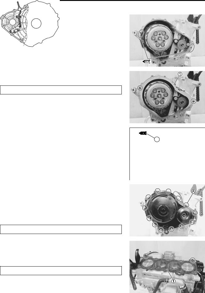
OIL PRESSURE SWITCH
•Apply SUZUKI BOND to the thread part of oil pressure switch and tighten oil pressure switch to the specified torque.
99104-31140: SUZUKI BOND “1207B” (USA) |
|
|
E |
|
|
|
|
|
99000-31140: SUZUKI BOND “1207B” (Others) |
|
|
|
|
|
|
||
Oil pressure switch: 14 N·m (1.4 kgf-m, 10.0 lb-ft) |
P |
|
|
|
|
|||
NOTE: |
|
|
|
|
|
|||
|
|
|
|
|
||||
|
|
L |
|
|
|
|
||
Be careful not to apply SUZUKI BOND to the hole of thread end. |
|
|
|
|
|
|
||
|
M |
|
|
|
|
|
|
|
|
|
|
|
|
|
|
||
|
|
|
|
|
|
|
||
|
|
|
|
|
|
|
||
OIL COOLER |
A |
|
|
|
|
|
|
|
• Apply SUZUKI SUPER GREASE “ ” to the O-ring and install |
|
|
|
|
|
|
||
the oil cooler. |
S |
|
|
|
|
|
|
|
|
|
|
|
|
|
|
|
|
99000-25010: SUZUKI UPER GREASE “A”
(or equivalent grease)
•Apply THREAD LOCK to the bolts and tighten them to the specified torque.
99000-32110: THREAD LOCK SUPER “1322”
(or equivalent thread lock)
Oil cooler mounting bolt: 10 N·m (1.0 kgf-m, 7.0 lb-ft)
Use a new O-ring to prevent oil leakage.

ENGINE 3-79
OIL FILTER
• Install the oil filter with the special tool. ( 2-13)
09915-40610: Oil filter wrench
Oil filter: 20 N·m (2.0 kgf-m, 14.5 lb-ft)
CRANKCASE BREATHER COVER
• Install a new gasket 1.
• Install the crankcase breather cover 2. |
E |
|
|
Crankcase breather cover bolt: 10 N·m (1.0 kgf-m, 7.0 lb-ft) |
|
|
L |
|
P |
M |
|
A |
|
S |
|
GEAR POSITION SWITCH
• Apply SUZUKI SUPER GREASE “A” to the O-ring.
NOTE:
Align the gear position switch pin A with the gearshift cam hole
B.
99000-25010: SUZUKI SUPER GREASE “A”
(or equivalent grease)
• Install the gear position switch as shown.
Gear position switch bolt: 7 N·m (0.7 kgf-m, 5.0 lb-ft)

3-80 ENGINE
WATER PUMP
• Apply SUZUKI SUPER GREASE “A” to the O-ring.
Use a new O-ring to prevent oil leakage.
99000-25010: SUZUKI SUPER GREASE “A”
(or equivalent grease)
• Install the water pump.
NOTE:
Set the water pump shaft end A to the oil pump shaft B as shown.
•Tighten the water pump mounting bolts to the specified torque.
Water pump mounting bolt: 10 N·m (1.0 kgf-m, 7.0 lb-ft)
|
|
|
E |
|
|
|
L |
• Apply engine coolant to the O-ring. |
M |
||
P |
|||
|
A |
|
|
|
|
||
|
|
||
Use a new O-ring to prevent engine coolant leakage. |
|
||
|
|
|
|
|
S |
|
|
• Install the water inlet connector 1.
Water inlet connector bolt: 10 N·m (1.0 kgf-m, 7.0 lb-ft)

ENGINE 3-81
GENERATOR ROTOR AND STARTER DRIVEN GEAR
•Degrease the tapered portion A of generator rotor and also the crankshaft B. Use nonflammable cleaning solvent to wipe off oily or greasy matter and make these surfaces completely dry.
•Install the generator rotor onto the crankshaft.
•Install the rotor bolt.
•Hold the generator rotor with the special tool and tighten its bolt to the specified torque.
09930-44520: Rotor holder
Generator rotor bolt: 120 N·m (12.0 kgf-m, 87.0 lb-ft)
|
|
|
|
E |
|
|
|
L |
|
CAM CHAIN/CAM CHAIN TENSIONER/CAM CHAIN GUIDE |
|
|||
• Install the cam chain. |
|
|
P |
|
• Apply a small quantity of THREAD LOCK to the cam chain |
|
|||
tensioner bolt and cam chain guide bolt. |
|
|
||
• Install the cam chain tensioner 1. |
M |
|
||
A |
|
|
||
• Install the cam chain guide No. 1 |
2. |
|
|
|
99000-32050: THREAD LOCK “1342” |
|
|
||
S |
|
|
|
|
Cam chain tensioner bolt: 23 N·m (2.3 kgf-m, 16.5 lb-ft) |
|
|||
Cam chain guide No. 1 bolt: 23 N·m (2.3 kgf-m, 6.5 lb-ft)
•Install the CKP sensor rotor/cam chain drive sprocket onto the crankshaft.
NOTE:
When installing the cam chain drive sprocket, align the wide spline tooth A and B.
• Set the cam chain onto the teeth C.

3-82 ENGINE
• While holding the generator rotor with the special tool, tighten the CKP sensor rotor/cam chain drive sprocket bolt.
09930-44520: Rotor holder
CKP sensor rotor/cam chain drive sprocket bolt:
54 N·m (5.4 kgf-m, 39.0 lb-ft)
STARTER IDLE GEAR
• Install the starter idle gear No. 2 1 and shaft 2.
|
E |
• Apply SUZUKI BOND lightly to the mating surfaces A at the |
L |
|
|
parting line between the upper and lower crankcases. |
|
99104-31140: SUZUKI BOND “1207B” (USA) |
|
M |
|
99000-31140: SUZUKI BOND “1207B” (Others) P |
|
A |
|
S |
|
• Install the dowel pin 3 and gasket 4.
Use a new gasket to prevent oil leakage.
• Install the generator cover.
NOTE:
* Fit the clamp to the generator cover bolt B.
Generator cover bolt: 10 N·m (1.0 kgf-m, 7.0 lb-ft)

ENGINE 3-83
• Install the starter idle gear No. 1 shaft 5, thrust washer 6, bearing 7, starter idle gear No. 1 8, washer 9, and spring washer 0.
• Apply SUZUKI SUPER GREASE “A” to the O-ring.
99000-25010: SUZUKI SUPER GREASE “A”
(or equivalent grease)
|
|
E |
|
L |
|
• Install the starter idle gear cover and tighten its bolts to the |
|
|
specified torque. |
P |
|
|
|
|
Starter idle gear cover bolt: 10 N·m (1.0 kgf-m, 7.0 lb-ft) |
|
|
|
M |
|
|
A |
|
|
S |
|
GEARSHIFT SYSTEM
•Install the gearshift cam stopper 1, bolt 2, collar 3 and return spring 4.
NOTE:
Apply a small quantity of THREAD LOCK to the gearshift cam stopper bolt 2 and tighten it to the specified torque.
99000-32050: THREAD LOCK “1342”
Gearshift cam stopper bolt: 10 N·m (1.0 kgf-m, 7.0 lb-ft)
NOTE:
Hook the return spring end A to the stopper.
•Check that the gearshift cam stopper moves smoothly.
•Set the gearshift cam in the neutral position.

3-84 ENGINE
• Install the gearshift cam stopper plate 5.
NOTE:
Align the gearshift cam pin B with the gearshift cam stopper plate hole C.
•Apply a small quantity of THREAD LOCK to the gearshift cam stopper plate bolt and tighten it to the specified torque.
99000-32050: THREAD LOCK “1342”
Gearshift cam stopper plate bolt:
|
13 N·m (1.3 kgf-m, 9.5 lb-ft) |
|
• Install the washer 6 and gearshift shaft assembly 7. |
E |
|
|
|
L |
NOTE: |
P |
|
|
|
|
Pinch the gearshift arm stopper 8 with return spring ends. |
|
|
|
M |
|
|
A |
|
|
S |
|
• Install the washer 9 and snap ring 0.
OIL PUMP DRIVE SPROCKET
• Install the thrust washer onto the countershaft.
NOTE:
The chamfer side A of thrust washer should face the crankcase side.

ENGINE 3-85
• Install the oil pump drive sprocket 1 to the countershaft.
NOTE:
Teeth A on the sprocket must face the clutch side.
• Pass the chain between the oil pump drive and driven sprockets.
CLUTCH
• Install the primary driven gear assembly 1.
NOTE:
* Before assembling the clutch, adjust the clutch lifter. ( 3-40)
*If it is difficult to install the primary driven gear, rotate the crankshaft.
*Be sure to engage the oil pump drive sprocket with the primary
driven gear. |
|
|
E |
|||
|
|
L |
||||
• Install the bearing 2 and spacer 3, and apply engine oil to |
|
|
|
|
||
them. |
|
P |
|
|
|
|
|
|
|
|
|
|
|
• Install the thrust washer 4. |
M |
|
|
|
|
|
|
|
|
|
|
|
|
|
|
|
|
|
|
|
|
|
|
|
|
|
|
|
|
|
|
|
|
|
|
|
A |
|
|
|
|
|
|
|
|
|
|
|
|
|
|
|
|
|
|
|
S |
|
|
|
|
|
• Install the washer 5 to the clutch sleeve hub.
•Install the wave spring washers 6, clutch lifter driven cam 7 and clutch lifter drive cam 8.
NOTE:
*Apply a small quantity of MOLYBDENUM OIL SOLUTION to the contact surfaces of the clutch lifter drive cam 8 and driven cam 7.
MOLYBDENUM OIL SOLUTION

3-86 ENGINE
• Install the clutch sleeve hub assembly onto the countershaft.
• Install the washer 9 and spring washer 0.
NOTE:
* Before installing the washer 9, visually inspect the washer surface for wear and damage. If necessary, replace it with a new one.
* The conical curve side of spring washer 0 faces outside.
|
|
|
E |
|
||
|
|
|
|
|||
• Hold the clutch sleeve hub with the special tool. |
|
L |
||||
09920-53740: Clutch sleeve hub holder |
P |
|||||
|
|
|
|
|
|
|
• Tighten the clutch sleeve hub nut to the specified torque. |
|
|
|
|
|
|
M |
|
|
|
|
|
|
Clutch sleeve hub nut: 95 N·m (9.5 kgf-m, 68.7 lb-ft) |
|
|
|
|
|
|
A |
|
|
|
|
|
|
S |
|
|
|
|
|
|
• Lock the clutch sleeve hub nut with a center punch.
•Install the spring washer seat A and spring washer B onto the clutch sleeve hub correctly.

ENGINE 3-87
• Install the clutch push rod C into the countershaft.
• Install the clutch push piece D, bearing E and thrust washer F to the countershaft.
NOTE:
Thrust washer F is located between the pressure plate and bearing E.
|
|
|
|
E |
|
|
|
L |
|
• Insert the clutch drive plates and driven plates one by one into |
|
|||
the clutch sleeve hub in the prescribed order. |
|
|
||
NOTE: |
M |
|
|
|
|
|
|
||
Insert the outermost No. 2 drive plate claws |
B toPthe other slits |
|
||
C of clutch housing as shown. |
|
|
|
|
A |
|
|
|
|
S |
|
|
|
|
3-88 ENGINE
*1 |
*2 |
|
|
|
|
|
|
or |
|
|
|
|
|
|
|
*1: Direction of outside |
*2: Paint |
|
|
|
|
|
DRIVE PLATE: |
|
|
|
|
|
|
a No. 2 Drive plate....... 1 pc. [Black paint/I.D. 111 mm (4.4 in)] |
|
|
||||
b No. 1 Drive plate....... 6 pcs. [Purple paint/I.D. 111 mm (4.4 in)] |
|
|||||
c No. 3 Drive plate....... 1 pc. [NIL/I.D. 118 mm (4.6 in)] |
|
|
|
|||
NOTE: |
|
|
|
|
L |
|
No.3 drive plate can be distinguished by the inside diameter |
||||||
(I.D.). |
|
|
|
|
||
|
|
|
P |
E |
||
DRIVEN PLATE: (d + e |
= Total 7 pcs.) |
|
|
|||
|
|
|
|
|||
d No. 1 Driven plate (Thickness): 2.6 mm (0.102 in).....5 – 7 pcs. |
|
|||||
|
|
|
M |
|
|
|
e No. 2 Driven plate (Thickness): 2.3 mm (0.091 in).....2 – 0 pcs. |
|
|||||
• Install the pressure plate H. |
|
|
|
|
|
|
NOTE: |
S |
|
|
|
|
|
|
A |
|
|
|
||
When install the pressure plate, fit the convex part D of the |
|
|
||||
pressure plate onto the concave part E of the clutch sleeve hub. |
|
|
||||
•Install the clutch springs.
•Hold the clutch housing with the special tool.
Be careful not to damage the clutch housing or clutch plates.
09920-53740: Clutch sleeve hub holder
• Tighten the clutch spring set bolts to the specified torque.
Clutch spring set bolt: 10 N·m (1.0 kgf-m, 7.0 lb-ft)
NOTE:
*Tighten the clutch spring set bolts diagonally.
*After mounting the engine, adjust the push rod. ( 2-16)
ENGINE 3-89
CLUTCH COVER
•Apply SUZUKI BOND lightly to the mating surfaces at the parting line between the upper and lower crankcases as shown.
99104-31140: SUZUKI BOND “1207B” (USA)
99000-31140: SUZUKI BOND “1207B” (Others)
• Install new gasket 1 and dowel pin.
Use a new gasket to prevent oil leakage.
|
|
E |
|
|
|
|
|||
• Apply SUZUKI BOND lightly to the CKP sensor gromet. |
L |
|
|
|
|
|
|
|
|
P |
||||
99104-31140: SUZUKI BOND “1207B” (USA) |
|
|
|
|
99000-31140: SUZUKI BOND “1207B” (Others) |
|
|
|
|
M |
|
|
|
|
A |
|
|
|
|
S |
|
|
|
|
|
|
|
|
|
•Install the clutch cover and tighten its bolts to the specified torque.
Clutch cover bolt: 10 N·m (1.0 kgf-m, 7.0 lb-ft)
NOTE:
* Fit new gasket washer to the bolts A.
Use a new gasket washer to prevent oil leakage.
CYLINDER HEAD
•Fit the dowel pins and new cylinder head gasket 1 to the cylinder.
Use a new gasket to prevent gas leakage.

3-90 ENGINE
• Place the cylinder head on the cylinder.
NOTE:
When installing the cylinder head, keep the cam chain taut.
• Tighten the cylinder head bolts (M10) in the following four-step.
Step 1:
• Tighten the cylinder head bolts to the specified torque with a torque wrench sequentially and diagonally.
Step 2:
•Loosen all the cylinder head bolts diagonally. Step 3:
•Retighten the cylinder head bolts to the specified torque with a torque wrench sequentially and diagonally.
Step 4:
•Additionally tighten the cylinder head bolts with the specified angles diagonally using an angular torque gauge.
Cylinder head bolt (M10):
Step 1/Step 3 : 31 N·m (3.1 kgf-m, 22.5 lb-ft) |
|
|
E |
|||
|
|
|
|
|
||
Final step |
: 60° (1/6 turn) |
|
|
|
|
|
|
|
|
|
|
||
NOTE: |
|
|
L |
|||
|
|
P |
||||
Apply engine oil to the washers and thread portion of the bolts |
|
|
|
|
||
|
|
|
|
|||
before installing the cylinder head bolts. |
|
|
|
|
|
|
|
|
|
|
|
||
|
M |
|
|
|
|
|
|
A |
|
|
|
|
|
|
S |
|
|
|
|
|
|
|
|
|
|
|
|
• Tighten the cylinder head bolts to the specified torque.
Cylinder head bolt (M6): 10 N·m (1.0 kgf-m, 7.0 lb-ft)
• Fit the gasket 2 and tighten the ECT sensor.
ECT sensor: 18 N·m (1.8 kgf-m, 13.0 lb-ft)
ENGINE 3-91
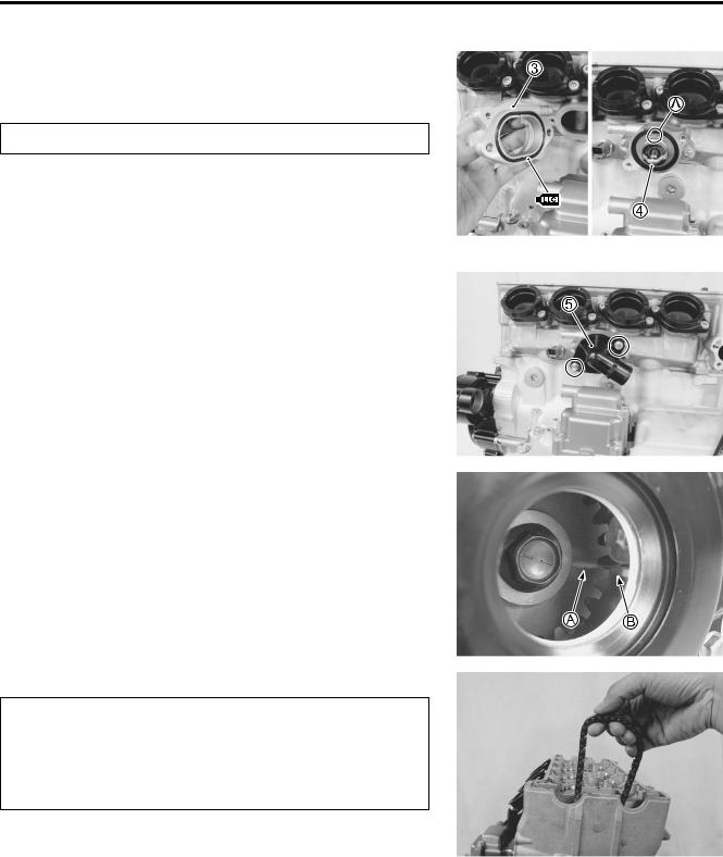
• Apply engine coolant to the O-ring.
• Install the thermostat conector 3.
Use a new O-ring to prevent engine coolant leakage.
Thermostat conector bolt: 10 N·m (1.0 kgf-m, 7.0 lb-ft)
• Install the thermostat 4.
NOTE:
The jiggle valve A of thermostat faces upside.
• Install the thermostat cover 5.
Thermostat cover bolt: 10 N·m (1.0 kgf-m, 7.0 lb-ft)
|
E |
|
L |
CAMSHAFT |
P |
|
|
• Turn the crankshaft clockwise with the box wrench and align |
|
the line A on the CKP sensor rotor to the rib B behind the |
|
|
M |
clutch cover while keeping the cam chain pulled upward. |
|
|
A |
|
S |
*Pull the cam chain upward, or the chain will be caught between crankcase and cam drive sprocket.
*To adjust the camshaft timing correctly, be sure to align the line A with B and hold this position when installing the camshafts.

3-92 ENGINE
The camshafts are identified by the embossed letters.
•Before replacing the camshafts on cylinder head, apply MOLYBDENUM OIL SOLUTION to their journals and cam faces.
•Apply a MOLYBDENUM OIL SOLUTION to the camshaft journal holders.
MOLYBDENUM OIL SOLUTION
NOTE:
Before installing the camshaft, check that the tappets are installed correctly.
• Pull the cam chain lightly. |
|
|
|
|
|
• The exhaust camshaft sprocket has an arrow marked “1” C. |
|
||||
Turn the exhaust camshaft so that the arrow is aligned with |
|
||||
the gasket surface of the cylinder head. |
|
|
|
|
|
• Engage the cam chain with the exhaust camshaft sprocket. |
|
||||
• Bind the cam chain and sprocket with a proper clamp 1 to |
E |
||||
prevent the cam chain disengagement while installing the |
|||||
|
|||||
camshaft journal holders. |
|
|
|
L |
|
• The other arrow marked “2” D should now be pointing straight |
|||||
|
|
P |
|
||
up. Starting from the roller pin that is directly above the arrow |
|
||||
marked “2” D, count out 12 roller pins (from the exhaust cam- |
|
||||
shaft side going towards the intake camshaft side). |
|
|
|
||
• Engage the 12th roller pin E on the cam chain with the arrow |
|
||||
A |
|
|
|
||
marked “3” on the intake sprocket. |
M |
|
|||
S |
|
|
2 to |
|
|
• Bind the cam chain and sprocket with a proper clamp |
|
||||
prevent the cam chain disengagement while installing the camshaft journal holders.
NOTE:
The cam chain should now be on all three sprockets. Be careful not to move the crankshaft until the camshaft journal holders and cam chain tension adjuster are secured.

ENGINE 3-93
• Install the dowel pins.
• Install O-rings 3 to the camshaft journal holders.
Replace the O-rings with new ones.
|
E |
• Install the camshaft journal holders. |
L |
|
NOTE:
* Each camshaft journal holder is identified with an embossed |
|
letter. |
P |
“A”: No.1 and No.2 cylinders |
|
A |
|
“B”: No.3 and No.4 cylinders |
M |
* Check that embossed letter on each holder faces exhaust |
|
|
S |
side. |
|
Damage to head or camshaft journal holder thrust surfaces may result if the camshaft journal holders are not drawn down evenly.
•Install the can chain guide No. 2 4.
•Fasten the camshaft journal holders evenly by tightening the camshaft journal holder bolts lightly, in the ascending order of numbers.
NOTE:
*Fit the copper washer to the camshaft journal holder bolts F.
*The ascending order of numbers are indicated on the camshaft journal holders.

3-94 ENGINE
•Tighten the camshaft journal holder bolts in the ascending order of numbers to the specified torque.
Camshaft journal holder bolt: 10 N·m (1.0 kgf-m, 7.0 lb-ft)
The camshaft journal holder bolts are made of a special material and much superior in strength, compared with other types of high strength bolts.
Take special care not to use other types of bolts.
12 |
|
|
|
|
|
|
|
|
|
|
16 |
14 |
|
8 |
|
|
|
10 |
|
26 |
(4) |
18 |
20 |
|
(2) |
22 |
E |
(6) |
24 |
25 |
(3) |
17 |
19 |
|
(1) |
21 |
(5) |
23 |
|
|
|
|
|
|
|
|
|
|
|
11 |
|
|
|
|
L |
|
|
||
15 |
13 |
|
7 |
|
|
|
9 |
||
|
|
|
|
P |
|
|
|
|
|
|
|
|
M |
|
|
|
|
|
|
|
|
A |
|
|
|
|
|
|
|
|
|
S |
|
|
|
|
|
|
|
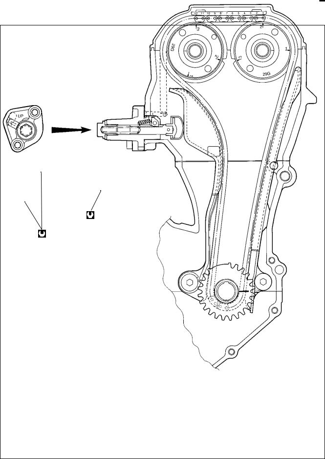
CAM CHAIN TENSION ADJUSTER |
|
|
|
|
|
|
|
||
• Retract the push rod by pushing the stopper 1. |
|
|
|
|
|
|
|||
• Fit a new gasket 2.
Use a new gasket to prevent oil leakage.
•Install the cam chain tension adjuster 3 and tighten its mounting bolts.
Cam chain tension adjuster mounting bolt:
10 N·m (1.0 kgf-m, 7.0 lb-ft)
• Install the spring 4.

ENGINE 3-95
•Install the gasket 5 and cam chain tension adjuster cap bolt
6.
NOTE:
Click sound is heard when the cam chain tension adjuster cap bolt is installed.
• Tighten the cam chain tension adjuster cap bolt to the specified torque.
Cam chain tension adjuster cap bolt:
23 N·m (2.3 kgf-m, 16.5 lb-ft)
After installing the cam chain tension adjuster, check to be sure that the adjuster works properly by checking the slack of cam chain.
•Remove the clamps.
•After installing the cam chain tension adjuster, rotate the
crankshaft (some turns), and recheck the positions of the |
|
camshafts. ( 3-96) |
L |
E |
|
|
P |
|
M |
|
A |
S |
|
3-96 ENGINE
|
|
23 N·m |
E |
|
|
|
L |
||
|
|
(2.3 kgf-m, 16.5 lb-ft) |
||
|
|
|
||
10 N·m |
|
|
P |
|
(1.0 kgf-m, 7.0 lb-ft) |
|
|||
M |
||||
|
|
|||
|
|
A |
|
|
|
S |
|
||

ENGINE 3-97
•Tighten the valve timing inspection cap 7 to the specified torque.
Valve timing inspection cap: 11 N·m (1.1 kgf-m, 8.0 lb-ft)
CYLINDER HEAD COVER
• Pour engine oil in each oil pocket in the cylinder head.
NOTE:
Be sure to check the valve clearance. ( 2-7)
|
|
|
|
E |
|
|
|
|
|
|
|
|
|
|
|
|
|
• Install the PAIR reed valves 1 along with the gaskets. |
L |
|
|||
|
|
|
|
||
NOTE: |
|
|
|
|
|
Fit the projection of the gaskets to the depression of the cam- |
|
|
|||
|
M |
|
|
|
|
shaft holders. |
P |
|
|
||
|
|
|
|
|
|
|
A |
|
|
|
|
Replace the gaskets with new ones. |
|
|
|
|
|
|
S |
|
|
|
|
•Install a new gasket to the cylinder head cover.
•Apply SUZUKI BOND to the cam end cap points of the gasket as shown.
99104-31140: SUZUKI BOND “1207B” (USA)
99000-31140: SUZUKI BOND “1207B” (Others)
Use a new gasket to prevent oil leakage.
•Place the cylinder head cover on the cylinder head.
•Fit a new gasket 2 to each head cover bolt.
Use new gaskets to prevent oil leakage.
3-98 ENGINE
• Tighten the head cover bolts to the specified torque.
Head cover bolt: 14 N·m (1.4 kgf-m, 10.0 lb-ft)
STARTER MOTOR
• Apply SUZUKI SUPER GREASE “A” to the O-ring.
99000-25010: SUZUKI SUPER GREASE “A”
(or equivalent grease)
|
E |
• Install the starter motor 1. |
L |
P |
|
Starter motor mounting bolt: 6 N·m (0.6 kgf-m, 4.5 lb-ft) |
|
M |
|
A |
|
S |
|
• Install the spark plugs. ( 2-6)