


5-2 FUEL SYSTEM AND THROTTLE BODY
FUEL DELIVERY SYSTEM
The fuel delivery system consists of the fuel tank, fuel pump, fuel filters, fuel feed hose, fuel delivery pipe (including fuel injectors) and fuel pressure regulator. There is no fuel return hose. The fuel in the fuel tank is pumped up by the fuel pump and pressurized fuel flows into the injector installed in the fuel delivery pipe. Fuel pressure is regulated by the fuel pressure regulator. As the fuel pressure applied to the fuel injector (the fuel pressure in the fuel delivery pipe) is always kept at absolute fuel pressure of 3.0 kgf/cm2 (300 kPa, 43 psi), the fuel is injected into the throttle body in conic dispersion when the injector opens according to the injection signal from the ECM.
The fuel relieved by the fuel pressure regulator flows back to the fuel tank.
E |
L |
P |
M |
A |
S |
1 |
Fuel tank |
7 |
Fuel feed hose |
|
|
|
|
2 |
Fuel filter (For high pressure) |
8 |
Fuel mesh filter (For low pressure) |
|
|
|
|
3 |
Fuel pressure regulator |
9 |
Fuel pump |
|
|
|
|
4 |
Fuel delivery pipe |
A |
Before-pressurized fuel |
|
|
|
|
5 |
Primary fuel injector |
B |
Pressurized fuel |
|
|
|
|
6 |
Secondary fuel injector |
C |
Relieved fuel |
FUEL SYSTEM AND THROTTLE BODY 5-3
FUEL SYSTEM
FUEL TANK LIFT-UP
•Remove the seats. ( 8-7 and -8)
•Take out the fuel tank prop stay 1.
• Remove the fuel tank bolt.
E L • Lift and support the fuel tank with the fuel tank propPstay.
M
A
S

5-4 FUEL SYSTEM AND THROTTLE BODY
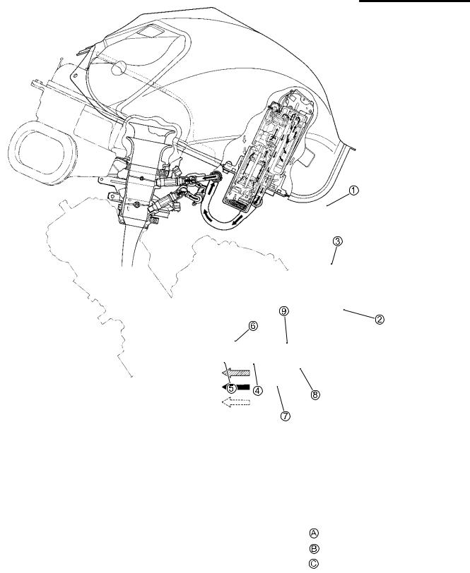
FUEL TANK REMOVAL
• Lift and support the fuel tank. ( above)
• Disconnect the fuel pump lead wire coupler 1.
• Disconnect the fuel tank breather hose 2 and fuel tank drain hose 3.
• Place a rag under the fuel feed hose 4 and disconnect the fuel feed hose.
When removing the fuel tank, do not leave the fuel feed hose 4 on the fuel tank side.
Gasoline is highly flammable and explosive.
Keep heat, spark and flame away.
•Remove the fuel tank bracket mounting bolt.
•Remove the fuel tank.
E L P M
FUEL TANK INSTALLATIONSA
• Installation is in the reverse order of removal.
FUEL PRESSURE INSPECTION
•Lift and support the fuel tank. ( 5-3)
•Place a rag under the fuel feed hose 1 and remove the fuel feed hose.

FUEL SYSTEM AND THROTTLE BODY 5-5
•Install the special tools between the fuel tank and fuel delivery pipe.
09940-40211: Fuel pressure gauge adaptor
09940-40220: Fuel pressure gauge hose attachment
09915-77331: Oil pressure gauge
09915-74521: Oil pressure gauge hose
Turn the ignition switch ON and check the fuel pressure.
Fuel pressure: Approx. 300 kPa (3.0 kgf/cm2, 43 psi)
If the fuel pressure is lower than the specification, inspect the |
|||||
following items: |
|
|
|
|
|
* Fuel hose leakage |
|
|
|
|
|
* Clogged fuel filter |
|
|
|
|
|
* Pressure regulator |
|
|
|
|
|
* Fuel pump |
|
|
|
|
|
If the fuel pressure is higher than the specification, inspect the |
|
||||
following items: |
|
|
|
|
E |
* Fuel pump check valve |
|
|
|
||
* Pressure regulator |
|
|
|
|
|
|
|
|
|
|
|
* Before removing the special tools, turn the ignition |
|
|
|||
|
|
|
L |
||
switch to OFF position and release the fuel pressure |
|||||
slowly. |
|
|
P |
||
* Gasoline is highly flammable and explosive. Keep |
|||||
heat, sparks and flame away. |
M |
||||
|
|
A |
|
|
|
A To fuel tank |
|
||||
B To fuel delivery pipe |
|
|
|
|
|
|
S |
|
|
|
|
|
|
|
|
||
FUEL PUMP INSPECTION
Turn the ignition switch ON and check that the fuel pump operates for few seconds.
If the fuel pump motor does not make operating sound, inspect the fuel pump circuit connections or inspect the fuel pump relay and to sensor.
If the fuel pump relay, to sensor and fuel pump circuit connections are OK, the fuel pump may be faulty, replace the fuel pump with a new one.

5-6 FUEL SYSTEM AND THROTTLE BODY
FUEL DISCHARGE AMOUNT INSPECTION
Gasoline is highly flammable and explosive.
Keep heat, spark and flame away.
• Lift and support the fuel tank. ( 5-3)
•Turn the ignition switch OFF.
•Disconnect the battery - lead wire.
•Place a rag under the fuel feed hose and disconnect the fuel feed hose 1 from the fuel pump.
•Connect a proper fuel hose 2 to the fuel pump.
|
|
E |
|
|
L |
|
P |
|
• Place the measuring cylinder and insert the fuel hose end into |
|
|
the measuring cylinder. |
M |
|
|
|
|
|
A |
|
|
S |
|
• Disconnect the fuel pump lead wire coupler 3.

FUEL SYSTEM AND THROTTLE BODY 5-7
•Connect a proper lead wire to the fuel pump lead wire coupler (fuel pump side) and apply 12 V to the fuel pump (between Y/R wire and B/W wire) for 10 seconds and measure the amount of fuel discharged.
Battery + terminal 
 (Y/R terminal) Battery - terminal
 (B/W terminal)
If the pump does not discharge the amount specified, it means that the fuel pump is defective or that the fuel filter is clogged.
Fuel discharge amount:
168 ml (5.7/5.9 US/Imp oz) and more/10 sec.
NOTE:
The battery must be in fully charged condition.
FUEL PUMP RELAY INSPECTION
Fuel pump relay is located on the air cleaner box (right side
one). |
|
|
E |
|
• Lift and support the fuel tank. ( 5-3) |
|
|
||
|
L |
|||
• Remove the fuel pump relay 1. |
|
|||
|
|
|
|
|
First, check the insulation between A and B terminals with |
|
|
||
|
P |
|
|
|
pocket tester. Then apply 12 V to C and D terminals, + to C |
|
|
||
and - to D, and check the continuity between A and B. |
|
|
|
|
M |
|
|
|
|
If there is no continuity, replace it with a new one. |
|
|
|
|
A |
|
|
|
|
|
|
|
|
|
S |
|
|
|
|
|
|
|
|
|


5-10 FUEL SYSTEM AND THROTTLE BODY
• Remove the fuel mesh filter 7.
•Remove the fuel pump 8 from the fuel pump case/fuel filter cartridge 9.
replace the fuel filter cartridge with a new one.
FUEL MESH FILTER INSPECTION AND |
|
E |
|
CLEANING |
|
|
L |
If the fuel mesh filter is clogged with sediment or rust, fuel will |
|||
not flow smoothly and loss in engine power may result. |
P |
||
Blow the fuel mesh filter with compressed air. |
|
|
|
NOTE: |
M |
|
|
|
|
|
|
If the fuel mesh filter is clogged with many sediment or rust, |
|
||
|
A |
|
|
|
S |
|
|
FUEL PUMP AND FUEL MESH FILTER INSTALLATION
Install the fuel pump and fuel mesh filter in the reverse order of removal. Pay attention to the following points:
• Install new bushing 1 to the fuel pump.
Use new bushing to prevent fuel leakage.
•Install new O-ring to the fuel pipe.
•Apply thin coat of engine oil to the new O-ring.
Use new O-ring to prevent fuel leakage.

FUEL SYSTEM AND THROTTLE BODY 5-11
• Be sure to connect the wires to the proper terminals. A (Bl) ........ + terminal for fuel pump
B (R)......... + terminal for fuel level gauge
E
L
P
M
A
S
•Install a new O-ring and apply SUZUKI SUPER GREASE “A” to it.
99000-25010: SUZUKI SUPER GREASE “A”
(or equivalent grease)
The O-ring must be replaced with a new one to prevent fuel leakage.

5-12 FUEL SYSTEM AND THROTTLE BODY
• When installing the fuel pump assembly, first tighten all the fuel pump mounting bolts lightly and then to the specified torque, in the ascending order of numbers.
Fuel pump mounting bolt: 10 N·m (1.0 kgf-m, 7.0 lb-ft)
NOTE:
Apply a small quantity of the THREAD LOCK to the thread portion of fuel pump mounting bolts.
99000-32050: THREAD LOCK “1342”
E
L
P
M
A
S