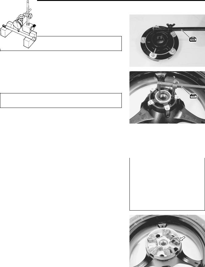
- •HOW TO USE THIS MANUAL
- •TO LOCATE WHAT YOU ARE LOOKING FOR:
- •COMPONENT PARTS AND WORK TO BE DONE
- •SYMBOL
- •ABBREVIATIONS USED IN THIS MANUAL
- •01 GENERAL INFORMATION
- •COUNTRY AND AREA CODES
- •WARNING/CAUTION/NOTE
- •GENERAL PRECAUTIONS
- •SUZUKI GSX-R600K6 (’06-MODEL)
- •SERIAL NUMBER LOCATION
- •FUEL, OIL AND ENGINE COOLANT RECOMMENDATION
- •BREAK-IN PROCEDURES
- •CYLINDER IDENTIFICATION
- •INFORMATION LABELS
- •SPECIFICATIONS
- •02 PERIODIC MAINTENANCE
- •PERIODIC MAINTENANCE SCHEDULE
- •MAINTENANCE AND TUNE-UP PROCEDURES
- •COMPRESSION PRESSURE CHECK
- •SDS CHECK
- •03 ENGINE
- •ENGINE COMPONENTS REMOVABLE WITH ENGINE IN PLACE
- •ENGINE REMOVAL AND INSTALLATION
- •ENGINE DISASSEMBLY
- •ENGINE REASSEMBLY
- •04 FI SYSTEM DIAGNOSIS
- •PRECAUTIONS IN SERVICING
- •FI SYSTEM TECHNICAL FEATURES
- •ECM TERMINAL
- •SELF-DIAGNOSIS FUNCTION
- •FAIL-SAFE FUNCTION
- •FI SYSTEM TROUBLESHOOTING
- •SENSORS
- •05 FUEL SYSTEM AND THROTTLE BODY
- •FUEL DELIVERY SYSTEM
- •FUEL SYSTEM
- •THROTTLE BODY
- •06 EXHAUST SYSTEM
- •EXHAUST SYSTEM
- •EXCVA (EXHAUST CONTROL VALVE ACTUATOR) AND EXCV (EXHAUST CONTROL VALVE)
- •07 COOLING AND LUBRICATION SYSTEM
- •ENGINE COOLANT
- •COOLING CIRCUIT
- •COOLING FAN
- •ECT SENSOR
- •THERMOSTAT
- •WATER PUMP
- •LUBRICATION SYSTEM
- •08 CHASSIS
- •EXTERIOR PARTS
- •FRONT WHEEL
- •FRONT FORK
- •STEERING DAMPER
- •STEERING
- •HANDLEBARS
- •REAR WHEEL
- •REAR SHOCK ABSORBER
- •REAR SUSPENSION
- •FRONT BRAKE
- •REAR BRAKE
- •TIRE AND WHEEL
- •DRIVE CHAIN
- •09 ELECTRICAL SYSTEM
- •CAUTIONS IN SERVICING
- •LOCATION OF ELECTRICAL COMPONENTS
- •CHARGING SYSTEM
- •STARTER SYSTEM AND SIDE-STAND/IGNITION INTERLOCK SYSTEM
- •IGNITION SYSTEM
- •COMBINATION METER
- •LAMPS
- •RELAYS
- •BATTERY
- •10 SERVICING INFORMATION
- •TROUBLESHOOTING
- •WIRING HARNESS, CABLE AND HOSE ROUTING
- •TIGHTENING TORQUE
- •SERVICE DATA
- •11 EMISSION CONTROL INFORMATION
- •EMISSION CONTROL SYSTEMS
- •PAIR (AIR SUPPLY) SYSTEM AND EMISSION CONTROL SYSTEM INSPECTION
- •PAIR (AIR SUPPLY) SYSTEM HOSE ROUTING
- •HO2 SENSOR INSPECTION (For E-02, 19)
- •12 WIRING DIAGRAM
8-40 CHASSIS
REAR WHEEL
CONSTRUCTION
E |
L |
P |
M |
A |
S |
1*
1 |
Rear axle |
0 |
Sprocket mounting drum |
|
|
|
|
2 |
Brake disc |
A |
Sprocket |
|
|
|
|
3 |
Collar |
B |
Bearing |
|
|
|
|
4 |
Dust seal |
C |
Dust seal |
|
|
|
|
5 |
Rear wheel |
D |
Collar |
|
|
|
|
6 |
Spacer |
A |
Brake disc bolt |
|
|
|
|
7 |
Bearing |
B |
Rear sprocket nut |
|
|
|
|
8 |
Cushion |
C |
Rear axle nut |
|
|
|
|
9 |
Spacer |
*1 |
Except for E-03, 28, 33 |
|
|
|
|
ITEM |
N·m |
kgf-m |
lb-ft |
|
|
|
|
A |
35 |
3.53 |
25.5 |
|
|
|
|
B |
93 |
9.3 |
67.5 |
|
|
|
|
C |
100 |
10.0 |
72.5 |
|
|
|
|
CHASSIS 8-41
REMOVAL
•Remove the cotter pin. (For E-03, 28, 33)
•Loosen the axle nut 1.
• Remove the under cowling. ( 8-5)
•Raise the rear wheel off the ground and support the motorcycle with a jack or wooden block.
•Remove the axle nut and draw out the rear axle.
•Remove the rear wheel by disengaging the drive chain.
Do not operate the brake pedal with the rear wheel removed.
|
E |
• Remove the collar 2. |
L |
• Remove the brake disc bolts 3. |
P |
• Remove the brake disc 4. |
|
|
M |
A |
|
S |
|
•Remove the collar 5.
•Loosen the rear sprocket mounting bolts 6 and separate the rear sprocket 7 from its mounting drum 8.
•Draw out the rear sprocket mounting drum 8 from the wheel hub.
• Remove the rear sprocket mounting drum retainer 9.
8-42 CHASSIS
• Remove the dust seal with the special tool.
09913-50121: Oil seal remover
The removed dust seal must be replaced with a new one.
• Remove the dust seal with the special tool.
09913-50121: Oil seal remover
The removed dust seal must be replaced with a new one.
|
|
|
|
|
E |
|
|
|
|
L |
|
INSPECTION AND DISASSEMBLY |
P |
||||
|
|
|
|||
TIRE INSPECTION ( 2-x and 8-85) |
M |
|
|
||
WHEEL INSPECTION ( 8-85) |
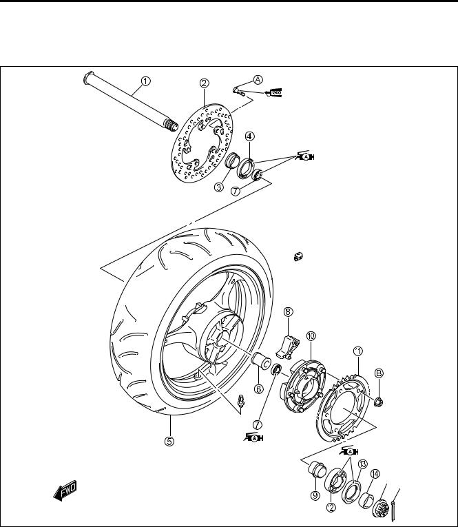
|
|
|||
|
|
|
|
||
REAR AXLE |
|
|
|
|
|
|
|
|
|
|
|
• Using a dial gauge, check the rear axle for runout. |
|
|
|
||
|
Service |
|
|
|
|
• If the runout exceeds the limit, replaceAthe rear axle. |
|
|
|
||
Axle shaft runout: |
Limit: 0.25 mm (0.010 in) |
|
|
09900-20607: Dial gauge (1/100 mm)
09900-20701: Magnetic stand
09900-21304: V-block set (100 mm)
WHEEL DAMPER
•Inspect the damper for wear and damage.
•Replace the damper if there is anything unusual.
CHASSIS 8-43
SPROCKET
• Inspect the sprocket teeth for wear.
• If they are worn as shown, replace the two sprockets and drive chain as a set.
A Normal wear
B Excessive wear
BEARINGS
• Inspect the play of the wheel bearing and sprocket mounting drum bearing by hand while they are installed in place. Rotate the inner race by hand to inspect for abnormal noise and smooth rotation.
• Replace the bearing if there is anything unusual.
|
|
|
E |
||
|
|
L |
|||
• Remove the sprocket mounting drum bearing with the special |
|
|
|
||
tool. |
|
P |
|
|
|
|
|
|
|
|
|
09913-70210: Bearing installer set |
|
|
|
|
|
|
M |
|
|
|
|
|
A |
|
|
|
|
|
S |
|
|
|
|
• Remove the wheel bearings with the special tool.
09921-20240: Bearing remover set
The removed bearings must be replaced with the new ones.
8-44 CHASSIS
REASSEMBLY AND INSTALLATION
Reassemble and install the rear wheel in the reverse order of removal and disassembly. Pay attention to the following points:
Left |
Right |
93 N·m
(9.3 kgf-m, 67.5 lb-ft)
35 N·m
(3.5 kgf-m, 25.5 lb-ft)
100 N·m
(10.0 kgf-m, 72.5 lb-ft)
|
E |
|
L |
|
P |
|
M |
|
A |
E-02, 19, 24 |
S |
|
E-03, 28, 33
100 N·m
(10.0 kgf-m, 72.5 lb-ft)
CHASSIS 8-45
BEARINGS
•Apply SUZUKI SUPER GREASE “A” to the bearings before installing.
99000-25010: SUZUKI SUPER GREASE “A”
(or equivalent grease)
• Install the new bearing to the sprocket mounting drum with the special tool.
09913-70210: Bearing installer set
|
|
|
|
|
E |
|
||
|
|
|
|
|
||||
|
|
L |
|
|||||
• First install the right wheel bearing, then install the left wheel |
|
|
|
|
|
|||
bearing with the special tools. |
|
|
|
|
|
|
|
|
09941-34513: Steering race installer |
|
|
|
|
|
|
|
|
|
|
|
|
|
|
|
||
|
M |
|
|
|
|
|
||
09924-84510: Bearing installer set |
P |
|
|
|
|
|
||
|
|
|
|
|
|
|
|
|
|
A |
|
|
|
|
|
|
|
The sealed cover of the bearing must face outside. |
|
|
|
|
|
|
||
|
S |
|
|
|
|
|
|
|
|
|
|
|
|
|
|
|
|
Left |
Right |
|
|
Left |
Right |
Spacer
Clearance
8-46 CHASSIS
WHEEL DAMPER
•To install the wheel dampers, apply a special tire lubricant or neutral soapy liquid to the damper surface.
*Never use oil, grease or gasoline on the damper in place of the tire lubricant.
DUST SEALS
• Install the new dust seal with the special tool.
09913-70210: Bearing installer set
|
E |
• Apply SUZUKI SUPER GREASE “A” to the dust seal lip |
L |
|
|
before assembling rear wheel. |
|
99000-25010: SUZUKI SUPER GREASE “A” |
|
M |
|
(or equivalent Pgrease) |
|
A |
|
S |
|
REAR SPROCKET AND SPROCKET MOUNTING DRUM
•Install the rear sprocket mounting drum spacer 1.
•Install the rear sprocket mounting drum to the rear wheel.
• Tighten the sprocket mounting nuts 2 to the specified torque.
Rear sprocket nut: 93 N·m (9.3 kgf-m, 67.5 lb-ft)
NOTE:
Stamped mark A on the sprocket should face outside.
• Install the collar 3.
CHASSIS 8-47
BRAKE DISC
• Apply THREAD LOCK to the disc bolts and tighten them to the specified torque.
NOTE:
Make sure that the brake disc is clean and free of any greasy matter.
99000-32130: THREAD LOCK SUPER “1360”
Brake disc bolt: 35 N·m (3.5 kgf-m, 25.5 lb-ft)
• Install the collar 1.
REAR AXLE
• Remount the rear wheel and rear axle shaft, and install the washer 1 (Except for E-03, 28, 33) and rear axle nut 2.
• Adjust the chain slack after rear wheel installation. ( 2-20)
E
L
P
M
A
S