

8-54 |
CHASSIS |
|
|
|
|
|
|
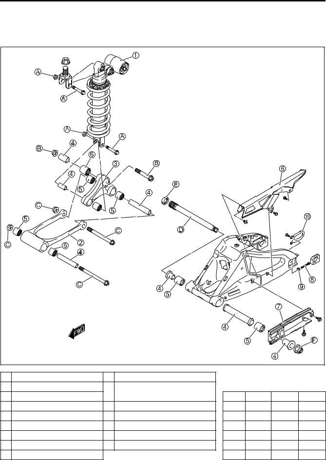
REAR SUSPENSION |
|
|
|
|
|
||
CONSTRUCTION |
|
|
|
|
|
|
|
|
|
|
|
E |
|
|
|
|
|
|
L |
|
|
|
|
|
|
|
P |
|
|
|
|
|
|
|
M |
|
|
|
|
|
|
A |
|
|
|
|
|
|
|
S |
|
|
|
|
|
1 |
Rear shock absorber |
0 |
Plate |
|
|
|
|
2 |
Rear cushion rod |
A |
Rear shock absorber mounting |
|
N·m |
kgf-m |
lb-ft |
3 |
Rear cushion lever |
|
bolt/nut |
ITEM |
|||
4 |
Spacer |
B Rear cushion lever bolt/nut |
A |
50 |
5.0 |
36.0 |
|
5 |
Bearing |
C Rear cushion rod bolt/nut |
B |
98 |
9.8 |
71.0 |
|
6 |
Chain cover |
D Swingarm pivot shaft |
C |
78 |
7.8 |
56.5 |
|
7 |
Chain buffer |
E Swingarm pivot lock nut |
D |
15 |
1.5 |
11.0 |
|
8 |
Chain adjuster |
F Swingarm pivot nut |
E |
90 |
9.0 |
65.0 |
|
9 |
Chain adjuster lock-nut |
|
|
F |
100 |
10.0 |
72.5 |


8-56 CHASSIS
• Remove the plate 0.
INSPECTION
SWINGARM PIVOT SHAFT
•Using a dial gauge, check the pivot shaft runout and replace it if the runout exceeds the limit.
Swingarm pivot shaft runout: |
|
|
|
|
|
Service limit: 0.3 mm (0.01 in) |
|
|
|
09900-20607: Dial gauge (1/100 mm, 10 mm) |
|
E |
||
09900-20701: Magnetic stand |
|
|
||
09900-21304: V-block set (100 mm) |
|
|
||
|
L |
|||
CHAIN BUFFER |
|
|||
|
|
|
||
• Inspect the chain buffer for wear and damage. |
|
|
||
|
|
M |
|
|
• If any defects are found, replace the chain buffer withPa new |
||||
one. |
A |
|
|
|
|
|
|
||
|
S |
|
|
|
PLATE
•Inspect the plate for damage and excessive bend.
•If any defects are found, replace the plate with a new one.

CHASSIS 8-57
SWINGARM
•Inspect the swingarm for damage. If any damages are found, replace the swingarm with a new one.
CUSHION ROD
•Inspect the cushion rod for damage and distortion.
•If any defects are found, replace the cushion rod with a new one.
|
|
|
E |
CUSHION LEVER |
|
L |
|
• Inspect the cushion lever for damage. |
P |
|
|
• If any defects are found, replace the cushion lever with a new |
|
||
one. |
M |
|
|
|
|
||
|
A |
|
|
|
S |
|
|
SPACER
•Remove the spacers from swingarm.
•Remove the spacers from the cushion lever.
•Remove the spacer from cushion rod.
•Inspect the spacers for any flaws or other damage. If any defects are found, replace the spacers with new ones.

8-58 CHASSIS
SWINGARM BEARING
•Insert the spacer into bearing and check the play when moving the spacer up and down.
•If excessive play is noted, replace the bearing with a new one.
CUSHION ROD BEARING
•Insert the spacer into bearing and check the play when moving the spacer up and down.
•If excessive play is noted, replace the bearing with a new one.
|
|
E |
CUSHION LEVER BEARING |
|
L |
|
|
|
• Insert the spacer into bearing and check the play when mov- |
|
|
ing the spacer up and down. |
P |
|
|
|
|
• If excessive play is noted, replace the bearing with a new one. |
|
|
|
M |
|
|
A |
|
S |
|
|
CHASSIS 8-59
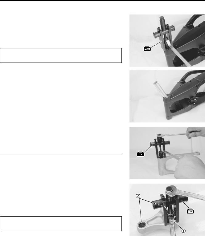
DISASSEMBLY
SWINGARM BEARING
• Draw out the swingarm pivot bearings with the special tool.
09921-20240: Bearing remover set (1 28 mm)
The removed bearings must be replaced with new ones.
• Remove the center spacer.
|
|
|
|
E |
||
CUSHION ROD BEARING |
|
L |
||||
|
|
|
|
|
||
• Draw out the cushion rod bearings with the special tool. |
|
|
|
|
||
|
|
P |
|
|
|
|
09921-20240: Bearing remover set |
|
|
|
|
|
|
|
M |
|
|
|
|
|
|
|
|
|
|
||
|
|
|
|
|
||
|
|
|
|
|
||
|
A |
|
|
|
|
|
The removed bearings must be replaced with new |
|
|
|
|||
ones. |
|
|
|
|
|
|
|
S |
|
|
|
|
|
CUSHION LEVER BEARING
• Draw out the cushion lever bearings with the special tool.
09921-20240: Bearing remover set (1 20 mm) (2 17 mm)
The removed bearings must be replaced with new ones.

8-60 CHASSIS
REASSEMBLY AND INSTALLATION
Reassemble and install the swingarm in the reverse order of disassembly and removal. Pay attention to the following points:
Left |
Right |
|
|
115 N·m |
|
|
(11.5 kgf-m, 83.0 lb-ft) |
|
|
50 N·m |
|
|
(5.0 kgf-m, 36.0 lb-ft) |
|
1 mm (0.04 in) |
1 mm (0.04 in) |
|
Apply SUZUKI SUPER GREASE “A” |
E |
78 N·m |
to the bearings, washers and dust seals. |
(7.8 kgf-m, 56.5 lb-ft) |
|
|
|
|
|
L |
|
P |
|
|
M |
50 N·m |
|
A |
(5.0 kgf-m, 36.0 lb-ft) |
|
|
||
S |
|
|
 78 N·m
(7.8 kgf-m, 56.5 lb-ft)
1 mm (0.04 in) |
1 mm (0.04 in) |

 98 N·m
(9.8 kgf-m, 71.0 lb-ft)
NOTE:
When installing the bearing, stamped mark on the bearing must face outside.
CHASSIS 8-61
SWINGARM BEARING
•Install the center spacer.
•Press the bearings into the swingarm pivot with the special tool.
09941-34513: Steering race installer
NOTE:
When installing the bearing, stamped mark on the bearing must face outside.
CUSHION ROD BEARING
• Press the bearings into the cushion rod with the special tool.
09924-84521: Bearing installer set
NOTE:
When installing the bearing, stamped mark on the bearing must face outside.
|
|
|
E |
|
CUSHION LEVER BEARING |
L |
|
||
|
|
|
||
• Press the bearings into the cushion lever with the special tool. |
|
|
||
09924-84521: Bearing installer set |
P |
|
|
|
|
|
|
||
NOTE: |
|
|
|
|
When installing the bearing, stamped mark on the bearing must |
|
|
||
face outside. |
A |
|
|
|
M |
|
|
||
|
S |
|
|
|
|
|
|
|
|
|
|
|
|
|
• Apply SUZUKI SUPER GREASE “A” to the bearings, spacers.
99000-25010: SUZUKI SUPER GREASE “A”
(or equivalent grease)

8-62 CHASSIS
• Remount the plate 1.
•Remount the chain cases 2 chain buffer 3 and rear fender (lower) 4.
SWINGARM PIVOT THRUST CLEARANCE ADJUSTMENT |
L |
|||
E |
||||
|
P |
|||
Adjust swingarm pivot thrust clearance in the following procedure. |
|
|
|
|
• Insert the swingarm pivot shaft and tighten to the specified |
|
|
|
|
torque. |
M |
|
|
|
|
|
|
|
|
|
|
|
|
|
09944-28320: Hexagon socket (19 mm) |
|
|
|
|
|
A |
|
|
|
Swingarm pivot shaft: 15 N·m (1.5 kgf-m, 11.0 lb-ft) |
|
|
|
|
|
S |
|
|
|
•Hold the swingarm pivot shaft and tighten the swingarm pivot nut 1 to the specified torque.
Swingarm pivot nut: 100 N·m (10.0 kgf-m, 72.5 lb-ft)
•Tighten the swingarm pivot lock-nut to the specified torque with the special tool.
09940-14940: Swingarm pivot thrust adjuster socket wrench
Swingarm pivot lock-nut: 90 N·m (9.0 kgf-m, 65.0 lb-ft)

CHASSIS 8-63
SHOCK ABSORBER, CUSHION LEVER AND CUSHION ROD MOUNTING BOLT/NUT
• Install the cushion lever.
• Tighten the cushion lever mounting nut 1 to the specified torque.
Cushion lever mounting nut:
98 N·m (9.8 kgf-m, 71.0 lb-ft)
•Install the cushion rod.
•Tighten the cushion rod mounting nut 2 to the specified
torque.
Cushion rod mounting nut:
78 N·m (7.8 kgf-m, 56.5 lb-ft)
|
|
|
|
E |
• Install the rear shock absorber. ( 8-52) |
|
L |
||
• Connect the drive chain. ( 8-90 to -92) |
P |
|
||
|
|
|
||
|
M |
|
|
|
FINAL INSPECTION AND ADJUST ENT |
|
|
||
After installing the rear suspension and wheel, the following |
|
|||
adjustments are required before driving. |
|
|
|
|
S |
|
|
|
|
* Drive chain ( 2-20) |
A |
|
|
|
* Tire pressure ( 2-27) |
|
|
|
|