

GSX-R600
9 9 5 0 0 - 3 5 1 0 0 - 0 1 E

FOREWORD |
|
|
GROUP INDEX |
|
|
This manual contains an introductory description on |
|
|
|||
the SUZUKI GSX-R600 and procedures for its |
|
|
|||
|
1 |
||||
inspection/service and overhaul of its main compo- |
GENERAL INFORMATION |
||||
nents. |
|
|
|||
Other information considered as generally known is |
|
|
|||
|
|
||||
not included. |
|
|
PERIODIC MAINTENANCE |
2 |
|
Read the GENERAL INFORMATION section to |
|||||
familiarize yourself with the motorcycle and its main- |
|
|
|||
tenance. Use this section as well as other sections |
|
|
|||
|
3 |
||||
to use as a guide for proper inspection and service. |
ENGINE |
||||
This manual will help you know the motorcycle bet- |
|||||
|
|
||||
ter so that you can assure your customers of fast |
|
|
|||
|
|
||||
and reliable service. |
|
|
FI SYSTEM DIAGNOSIS |
4 |
|
|
|
|
|||
* This manual has been prepared on the basis |
|
|
|||
|
|
|
|
||
of the latest specifications at the time of publi- |
|
|
|
|
|
|
|
|
|
||
|
|
FUEL SYSTEM AND THROTTLE |
5 |
||
cation. If modifications have been made since |
|
|
|||
then, differences may exist between the con- |
|
|
BODY |
||
|
|
6 |
|||
tent of this manual and the actual motorcycle. |
|
|
E |
||
|
|
|
|
||
* Illustrations in this manual are used to show |
|
|
L |
|
|
|
|
|
|
||
the basic principles of operation and work |
|
|
EXHAUST SYSTEM |
|
|
procedures. They may not represent the |
|
|
|
|
|
actual motorcycle exactly in detail. |
|
P |
|
||
|
|
COOLING AND LUBRICATION |
7 |
||
* This manual is written for persons who have |
|
|
|||
M |
|
SYSTEM |
|||
enough knowledge, skills and tools, including |
|
|
|
||
special tools, for servicing SUZUKI motorcy- |
|
|
|
|
|
|
|
|
|
||
cles. If you do not have the proper knowledge |
|
|
|
|
|
S |
|
|
|
8 |
|
and tools, ask your authorizedASUZUKI |
|
|
CHASSIS |
||
motorcycle dealer to help you. |
|
|
|
|
|
|
|
|
|
|
|
|
|
|
ELECTRICAL SYSTEM |
9 |
|
Inexperienced mechanics or mechanics |
|
|
|
|
|
without the proper tools and equipment |
|
|
|
|
|
|
|
|
10 |
||
may not be able to properly perform the |
|
|
SERVICING INFORMATION |
||
services described in this manual. |
|
|
|||
|
|
|
|
||
Improper repair may result in injury to the |
|
|
|
|
|
|
|
|
|
||
mechanic and may render the motorcycle |
|
|
EMISSION CONTROL |
11 |
|
unsafe for the rider and passenger. |
|
|
INFORMATION |
||
|
|
|
|
||
|
|
|
|
|
|
|
|
|
|
|
|
|
|
|
WIRING DIAGRAM |
12 |
|
|
|
|
|
|
|
© COPYRIGHT SUZUKI MOTOR CORPORATION 2006
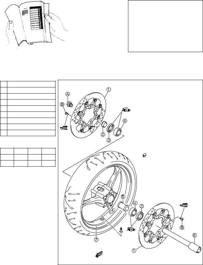
HOW TO USE THIS MANUAL
TO LOCATE WHAT YOU ARE LOOKING FOR:
1.The text of this manual is divided into sections.
2.The section titles are listed in the GROUP INDEX.
3.Holding the manual as shown at the right will allow you to find the first page of the section easily.
4.The contents are listed on the first page of each section to help you find the item and page you need.
COMPONENT PARTS AND WORK TO BE DONE
Under the name of each system or unit, is its exploded view. Work instructions and other service information such as the tightening torque, lubricating points and locking agent points, are provided.
Example: Front wheel
1 |
Brake disc |
|
E |
||
2 |
Collar |
|
|||
3 |
Dust seal |
|
|||
4 |
Bearing |
|
|||
5 |
Spacer |
|
L |
||
6 |
Front axle |
|
|||
|
P |
||||
7 |
Front wheel |
|
|||
A Front axle bolt |
M |
||||
B |
Brake disc bolt |
||||
A |
|||||
|
|
|
|
||
ITEM N·m kgf-m lb-ftS |
|||||
A |
100 |
10.0 |
72.5 |
||
B |
23 |
2.3 |
16.5 |
||
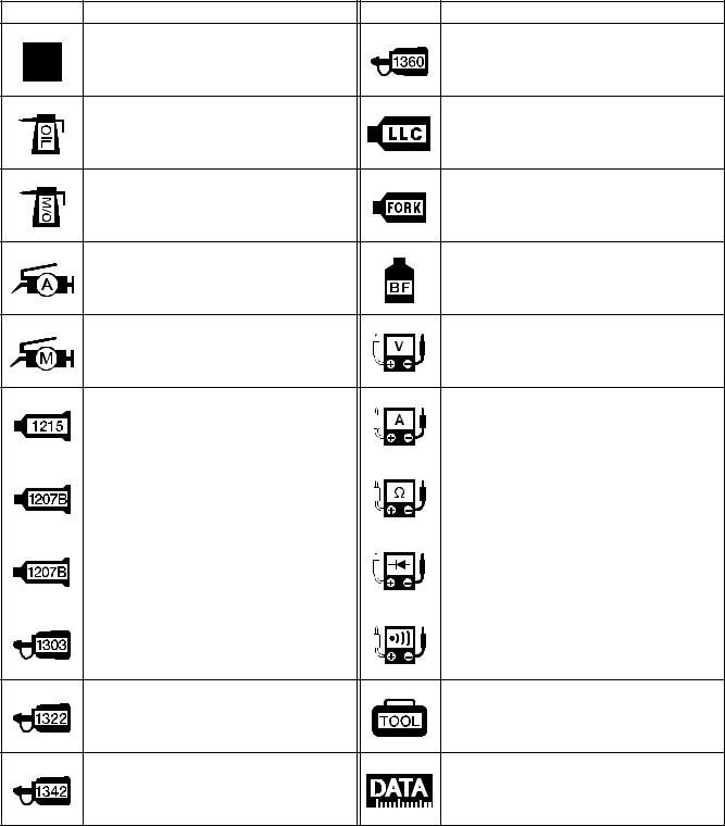
SYMBOL
Listed in the table below are the symbols indicating instructions and other information necessary for servicing. The meaning of each symbol is also included in the table.
SYMBOL |
DEFINITION |
SYMBOL |
DEFINITION |
Torque control required.
Data beside it indicates specified
Apply THREAD LOCK SUPER “1360”.
torque.
99000-32130
Apply oil. Use engine oil unless other- |
Use engine coolant. |
wise specified. |
99000-99032-11X (Except USA) |
Apply molybdenum oil solution. (Mixture of engine oil and SUZUKI
Use fork oil.
MOLY PASTE in a ratio of 1:1)
99000-99001-SS5
Apply SUZUKI SUPER GREASE “A” |
|
|
|||
or equivalent grease. |
|
|
Apply or use brake fluid. |
||
99000-25010 |
|
|
|
E |
|
|
|
|
|
|
|
Apply SUZUKI MOLY PASTE. |
|
L |
|||
99000-25140 |
|
|
|
Measure in voltage range. |
|
|
|
P |
|||
|
|
|
|
||
|
|
|
M |
|
|
Apply SUZUKI BOND “1215” |
|
|
|||
or equivalent bond. |
|
|
Measure in current range. |
||
99000-31110 |
|
|
|
|
|
|
|
|
|
|
|
Apply |
SUZUKI |
|
|
|
|
|
BONDA“1207B”. |
|
Measure in resistance range. |
||
99104-31140 (U A) |
|
|
|||
|
|
|
|||
|
|
|
|||
Apply SUZUKI BOND “1207B”. |
|
Measure in diode test range. |
|||
99000-31140 (Except USA) |
|
||||
|
|
||||
|
|
||||
Apply THREAD LOCK SUPER “1303”. |
Measure in continuity test range. |
||||
99000-32030 |
|
|
|
||
|
|
|
|
||
Apply THREAD LOCK SUPER “1322”
or equivalent thread lock. Use special tool. 99000-32110
Apply THREAD LOCK “1342”.
Indication of service data.
99000-32050