COOLING AND LUBRICATION SYSTEM 7-1
COOLING AND LUBRICATION SYSTEM
CONTENTS
|
ENGINE COOLANT |
..................................................................................... |
|
|
|
|
|
COOLING CIRCUIT ..................................................................................... |
|
|
|
|
|
|
COOLING CIRCUIT ........................................................INSPECTION |
|
|
|
|
RADIATOR AND WATER ..............................................................HOSES |
|
|
|
|
RADIATOR REMOVAL ......................................................................... |
|
|
|
|
|
RADIATOR CAP .............................................................INSPECTION |
|
|
|
|
RADIATOR INSPECTION .........................................AND CLEANING |
|
|
RADIATOR INSTALLATION................................................................. |
|
|
|
|
WATER HOSE INSPECTION................................................................ |
|
|
|
|
COOLING FAN............................................................................................. |
|
|
|
|
|
|
REMOVAL ............................................................................................. |
|
|
|
|
|
|
INSPECTION ......................................................................................... |
|
|
|
|
E |
|
INSTALLATION |
|
|
|
|
|
|
|
|
L |
|
COOLING FAN RELAY INSPECTION |
|
|
|
|
ECT SENSOR .............................................................................................. |
|
|
P |
|
|
REMOVAL |
|
|
|
|
|
|
|
|
|
|
INSPECTION ......................................................................................... |
|
M |
|
|
|
INSTALLATION |
|
|
|
|
A |
|
|
|
|
THERMOSTAT |
|
|
|
|
|
|
|
|
|
|
REMOVAL ............................................................................................. |
|
|
|
|
|
|
S |
|
|
|
|
INSPECTION .........................................................................................
INSTALLATION.....................................................................................
WATER PUMP .............................................................................................
REMOVAL AND DISASSEMBLY .........................................................
INSPECTION .........................................................................................
REASSEMBLY AND INSTALLATION ..................................................
LUBRICATION SYSTEM .............................................................................
OIL COOLER.........................................................................................
OIL PRESSURE ....................................................................................
OIL FILTER............................................................................................
OIL PRESSURE REGULATOR.............................................................
OIL STRAINER......................................................................................
OIL JET..................................................................................................
OIL PUMP..............................................................................................
OIL PRESSURE SWITCH .....................................................................
ENGINE LUBRICATION SYSTEM CHART ..........................................
ENGINE LUBRICATION SYSTEM........................................................
7- |
2 |
|
|
7- |
3 |
|
|
7- |
3 |
|
|
7- |
4 |
|
|
7- |
4 |
|
|
7- |
4 |
|
|
7- |
4 |
|
|
7- |
5 |
|
|
7- |
5 |
|
|
7- |
6 |
|
|
7- |
6 |
|
|
7- |
6 |
|
|
7- |
6 |
|
|
7- |
7 |
|
|
7- |
7 |
|
|
7- |
7 |
|
|
7- |
7 |
|
7 |
7- |
8 |
|
7- |
9 |
|
|
|
7- |
9 |
|
|
7- |
9 |
|
|
7-10 |
|
|
7-11 |
|
|
7-11 |
|
|
7-13 |
|
|
7-14 |
|
|
7-17 |
|
|
7-17 |
|
|
7-18 |
|
|
7-18 |
|
|
7-18 |
|
|
7-18 |
|
|
7-18 |
|
|
7-18 |
|
|
7-18 |
|
|
7-19 |
|
|
7-20 |
|
|
|
|
|
|
7-2 COOLING AND LUBRICATION SYSTEM
ENGINE COOLANT
At the time of manufacture, the cooling system is filled with a 50:50 mixture of distilled water and ethylene glycol anti-freeze. This 50:50 mixture will provide the optimum corrosion protection and excellent heat protection, and will protect the cooling system from freezing at temperatures above –31 °C (–24 °F).
If the motorcycle is to be exposed to temperatures below –31 °C (–24 °F), this mixing ratio should be increased up to 55% or 60% according to the figure.
Anti-freeze density |
Freezing point |
|
|
50% |
–30 °C (–24 °F) |
|
|
55% |
–40 °C (–44 °F) |
|
|
60% |
–55 °C (–67 °F) |
|
|
|
|
*Use a high quality ethylene glycol base anti-freeze, mixed with distilled water. Do not mix an alcohol base anti-freeze and different brands of anti-freeze.
*Do not put in 60% and more anti-freeze or 50% and less. (Refer to below figure.)
*Do not use a radiator anti-leak additive.
50% Engine coolant including reserve tank capacity |
|
|
|
|
E |
Anti-freeze |
|
|
1 350 ml (2.9/2.4 US/lmp.pt) |
|
L |
|
|
|
|
|
|
|
|
|
|
Water |
|
|
|
1 350 ml (2.9/2.4 US/lmp.pt) |
|
|
|
|
|
|
|
|
|
|
|
|
|
|
|
P |
|
|
|
|
|
|
(˚F) |
(˚C) |
|
|
M |
|
|
|
|
|
|
|
|
|
|
|
|
|
|
|
|
|
|
|
|
32 |
0 |
|
|
|
|
|
(˚F) (˚C) |
|
|
|
(kgf/cm²) |
|
|
|
|
|
|
|
|
|
|
14 |
–10 |
|
|
|
|
|
|
|
|
|
|
|
|
|
|
302 150 |
|
|
|
|
|
–4 |
–20 |
|
|
|
|
|
|
|
|
|
|
|
|
|
|
|
|
|
|
|
|
|
|
|
|
|
|
A |
|
|
284 140 |
|
|
|
|
|
|
|
–22 |
–30 |
|
|
|
|
|
|
|
|
|
|
|
|
|
|
|
|
|
|
|
|
|
pointFreezing |
|
S |
|
|
pointBoiling |
266 130 |
|
|
|
|
|
|
–40 |
–40 |
|
|
|
|
|
|
|
|
|
|
|
|
|
|
|
|
|
|
|
|
|
|
|
|
|
|
|
|
|
|
|
|
–58 |
–50 |
|
|
|
|
|
248 120 |
|
|
|
|
|
|
|
|
|
|
|
|
|
|
|
|
|
|
|
|
|
|
|
|
|
|
|
|
|
|
–76 |
–60 |
|
|
|
|
|
230 110 |
|
|
|
|
|
|
|
|
|
|
|
|
|
|
|
|
|
|
|
–94 |
–70 |
|
|
|
|
|
212 100 |
|
|
|
|
|
|
|
|
|
|
|
|
|
|
|
|
|
|
|
|
|
|
|
|
|
|
|
|
|
|
|
|
|
|
|
|
|
|
|
|
|
|
|
|
|
|
1.5 |
pressure |
|
0.9 |
|
|
|
0.5 |
Gauge |
|
0 |
|
|
20 |
40 |
60 |
80 |
100 |
0 |
10 |
20 |
30 |
40 |
50 |
60 |
|
Density (%) |
|
|
|
Density (%) |
|
|
Fig. 1 Engine coolant density-freezing point curve
Fig. 2 Engine coolant density-boiling point curve
*You can be injured by scalding fluid or steam if you open the radiator cap when the engine is hot. After the engine cools, wrap a thick cloth around cap and carefully remove the cap by turning it a quarter turn to allow pressure to escape and then turn the cap all the way off.
*The engine must be cool before servicing the cooling system.
*Coolant is harmful;
•If it comes in contact with skin or eyes, flush with water.
•If swallowed accidentally, induce vomiting and call physician immediately.
•Keep it away from children.
COOLING AND LUBRICATION SYSTEM 7-3
COOLING CIRCUIT
|
RESERVOIR |
THERMOSTAT |
CYLINDER HEAD |
ECT SENSOR |
|
TANK |
|
|
|
|
|
CYLINDER |
|
|
RADIATOR |
|
|
|
|
|
|
WATER |
|
|
|
|
PUMP |
|
|
|
|
Oil cooler |
|
COOLING CIRCUIT INSPECTION
|
Before removing the radiator and draining the engine coolant, |
E |
|
inspect the cooling circuit for tightness. |
|
|
|
L |
|
• Remove the right under cowling. ( 8-5) |
|
|
|
|
|
|
• Remove the radiator cap 1 and connect the tester 2 to the |
|
|
|
filler. |
|
P |
|
|
|
M |
|
|
|
|
|
|
|
Do not remove the radiator cap when the engine is |
|
|
|
|
hot. |
A |
|
|
|
|
|
S |
|
|
|
|
|
|
|
|
|
|
|
|
|
|
|
|
|
•Give a pressure of about 120 kPa (1.2 kgf/cm², 17 psi) and see if the system holds this pressure for 10 seconds.
•If the pressure should fall during this 10-second interval, it means that there is a leaking point in the system. In such a case, inspect the entire system and replace the leaking component or part.
When removing the radiator cap tester, put a rag on the filler to prevent spouting of engine coolant.
Do not allow the pressure to exceed the radiator cap release pressure, or the radiator can be damaged.
7-4 COOLING AND LUBRICATION SYSTEM
RADIATOR AND WATER HOSES
RADIATOR REMOVAL
• Remove the under cowlings. ( 8-5)
• Drain the engine coolant. ( 2-17)
• Remove the radiator assembly. ( 3-4)
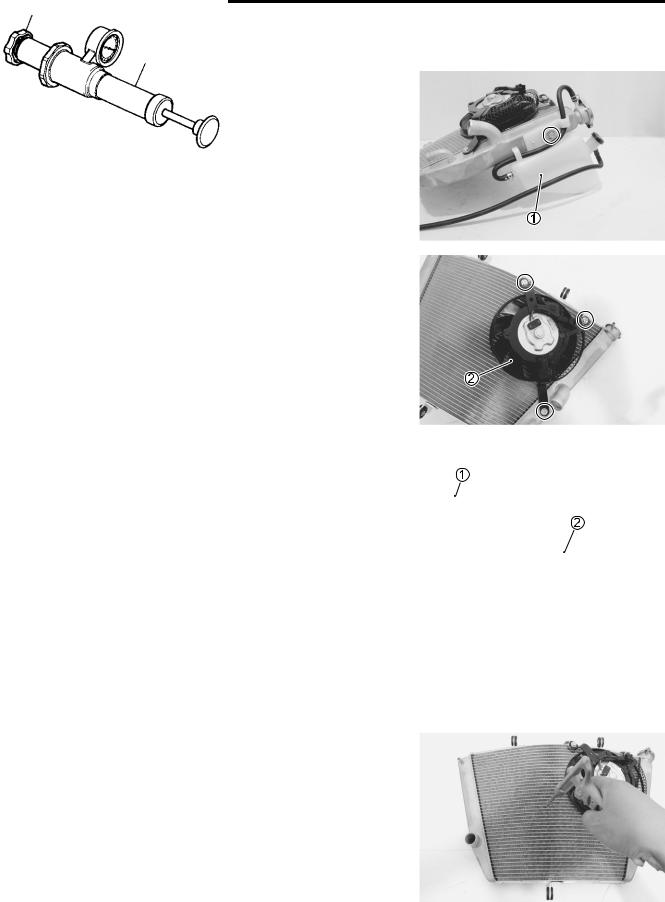
• Remove the reservoir tank 1, cooling fan 2 from the radiator.
|
|
|
E |
|
|
L |
RADIATOR CAP INSPECTION |
P |
|
• Fit the cap 1 to the radiator cap tester 2. |
|
• Build up pressure slowly by operating the tester. ake sure |
|
that the pressure build-up stops at 93 – 123MkPa (0.93 – 1.23 |
|
kgf/cm2, 13.2 – 17.5 psi) and that, with the tester held stand- |
|
|
A |
|
|
still, the cap is capable of holding that pressure for at least 10 |
|
seconds. |
S |
|
|
|
|
|
• Replace the cap if it is found not to satisfy either of these two |
|
requirements. |
|
|
|
Radiator cap valve opening pressure Standard: 108 – 137 kPa
(1.1 – 1.4 kgf/cm2, 15.4 – 19.5 psi)
RADIATOR INSPECTION AND CLEANING
Road dirt or trash stuck on the fins must be removed.
Use of compressed air is recommended for this cleaning.
COOLING AND LUBRICATION SYSTEM 7-5
Fins bent down or dented can be repaired by straightening them with the blade of a small screwdriver.
RADIATOR INSTALLATION
• Install the cooling fan.
Cooling fan mounting bolt: 8 N·m (0.8 kgf-m, 6.0 lb-ft)
•Install the radiator.
•Route the radiator hoses properly. ( 10-24)
•Pour engine coolant. ( 2-17)
•Bleed air from the cooling circuit. ( 2-18)
•Install the under cowlings. ( 8-5)
|
|
|
E |
|
WATER HOSE INSPECTION |
L |
|
P |
|
• Remove the under cowlings. ( 8-5) |
|
• Lift and support the fuel tank. ( 5-3) |
|
|
|
Any water hose found in a cracked condition or flattened must |
|
be replaced. |
M |
|
Any leakage from the connectingAsection should be corrected by |
|
proper tightening. |
S |
|
|
|
|