


ENGINE 3-1
ENGINE
CONTENTS
ENGINE COMPONENTS REMOVABLE WITH ENGINE IN PLACE ..........
ENGINE REMOVAL AND INSTALLATION.................................................
ENGINE REMOVAL ..............................................................................
ENGINE INSTALLATION ......................................................................
ENGINE DISASSEMBLY .............................................................................
ENGINE COMPONENTS INSPECTION AND SERVICE.............................
CYLINDER HEAD COVER.................................................................... |
|
|
|||
CMP SENSOR |
....................................................................................... |
|
|
|
|
PAIR REED VALVE............................................................................... |
|
|
|
||
CRANKCASE BREATHER ...........................................REED VALVE |
|
||||
PCV HOSE............................................................................................. |
|
|
|
|
|
CAMSHAFT ........................................................................................... |
|
|
|
E |
|
CAM CHAIN TENSION ADJUSTER |
|||||
L |
|||||
CAM CHAIN TENSIONER |
|
||||
|
|
||||
CAM CHAIN GUIDE .............................................................................. |
|
P |
|||
CYLINDER HEAD AND VALVE |
|||||
|
|
||||
CLUTCH ................................................................................................ |
|
M |
|
||
CLUTCH LIFTER |
|
||||
|
|
|
|||
OIL PUMP |
A |
|
|
||
|
|
|
|
||
STARTER CLUTCH .............................................................................. |
|
|
|
||
S |
|
|
|
||
GENERATOR ........................................................................................
WATER PUMP.......................................................................................
GEARSHIFT SYSTEM...........................................................................
OIL PRESSURE REGULATOR.............................................................
OIL STRAINER......................................................................................
TRANSMISSION....................................................................................
CYLINDER.............................................................................................
PISTON AND PISTON RING.................................................................
CRANKCASE ........................................................................................
CRANKSHAFT AND CONROD ............................................................
CRANKSHAFT JOURNAL BEARING ..................................................
CRANKSHAFT THRUST BEARING .....................................................
ENGINE REASSEMBLY ..............................................................................
3- 2
3- 3
3- 3
3-10
3-14 3
3-26
3-26
3-26
3-26
3-27
3-27
3-28
3-30
3-30
3-30
3-30
3-38
3-39
3-41
3-41
3-43
3-43
3-43
3-44
3-44
3-45
3-48
3-49
3-51
3-61
3-65
3-68
3-70

3-2 ENGINE
ENGINE COMPONENTS REMOVABLE WITH ENGINE IN PLACE
The parts listed below can be removed and reinstalled without removing the engine from the frame. Refer to page listed in each section for removal and reinstallation instructions.
ENGINE CENTER
ITEM |
REMOVAL |
INSPECTION |
INSTALLATION |
|
|
|
|
PAIR control solenoid valve |
11-7 |
11-7 |
11-7 |
Starter motor |
3-14 |
9-14 |
3-98 |
Breather cover |
3-22 |
— |
3-79 |
Thermostat |
7-9 |
7-9 |
7-10 |
Cylinder head cover |
3-14 |
— |
3-97 |
Camshaft |
3-14 |
3-28 |
3-91 |
Intake pipe |
3-37 |
— |
3-38 |
Oil filter |
3-22 |
— |
3-79 |
Oil cooler |
3-23 |
7-17 |
3-78 |
Oil pan |
3-23 |
— |
3-78 |
Oil pump |
3-23 |
3-41 |
3-77 |
ENGINE RIGHT SIDE |
|
|
|
|
E |
|
|
|
|
|
|
|
|
|
|
|
|
|
|
|
|
|
|
ITEM |
|
REMOVAL |
|
|
L |
|
INSTALLATION |
|
|
|
INSPECTION |
|
|||
Exhaust pipe and muffler |
|
3-5 |
|
|
— |
|
3-12 |
Cam chain tension adjuster |
3-15 |
|
P |
|
3-94 |
||
|
|
3-30 |
|
||||
Clutch cover |
|
3-16 |
|
|
— |
|
3-89 |
Clutch (plates) |
|
3-17 |
|
|
3-38 |
|
3-87 |
|
|
A |
|
|
3-39 |
|
3-85 |
Clutch lifter |
|
3M-18 |
|
|
|||
Primary driven gear |
|
3-18 |
|
|
3-39 |
|
3-85 |
Oil pump drive sprocket |
S |
|
|
— |
|
3-84 |
|
|
3-19 |
|
|
|
|||
Gearshift shaft |
|
3-19 |
|
|
3-43 |
|
3-83 |
CKP sensor |
|
3-16 |
|
|
4-35 |
|
3-89 |
Oil pump driven gear |
|
3-41 |
|
|
— |
|
— |
Cam chain tensioner |
|
3-20 |
|
|
3-30 |
|
3-81 |
Cam chain guide |
|
3-20 |
|
|
3-30 |
|
3-81 |
ENGINE LEFT SIDE |
|
|
|
|
|
|
|
|
|
|
|
|
|
|
|
ITEM |
|
REMOVAL |
|
|
INSPECTION |
|
INSTALLATION |
|
|
|
|
|
|
|
|
Engine sprocket |
|
3-7, 8 |
|
|
— |
|
3-12 |
Gear position switch |
|
3-22 |
|
|
4-75 |
|
3-79 |
Starter idle gear cover |
|
3-19 |
|
|
— |
|
3-83 |
Starter idle gear |
|
3-19, 20 |
|
|
— |
|
3-82, 83 |
Generator cover |
|
3-20 |
|
|
— |
|
3-82 |
Starter clutch |
|
3-21 |
|
|
3-41 |
|
3-81 |
Generator rotor |
|
3-21 |
|
|
— |
|
3-81 |
Water pump |
|
3-21 |
|
|
7-13 |
|
3-80 |

ENGINE 3-3
ENGINE REMOVAL AND INSTALLATION
ENGINE REMOVAL
Before taking the engine out of the frame, wash the engine using a steam cleaner. Engine removal is sequentially explained in the following steps. Reinstall the engine by reversing the removal procedure.
•Remove the under cowlings. ( 8-5)
•Lift and support the fuel tank. ( 5-3)
•Drain engine oil. ( 2-12)
•Drain engine coolant. ( 2-17)
•Disconnect the battery - lead wire 1.
|
|
E |
|
|
L |
• Remove the air cleaner box. ( 5-14) |
P |
|
M |
|
|
A |
|
|
S |
|
|
• Remove the throttle body assembly. ( 5-15)

3-4 ENGINE
RADIATOR
• Disconnect the by-pass hose 1 and radiator inlet hose 2.
• Disconnect the oil cooler outlet hose 3.
|
E |
• Disconnect the cooling fan coupler 4. |
L |
|
P |
|
M |
A |
|
S |
|
• Remove the radiator mounting bolts.
• Remove the radiator 5.
Be careful not to bent the radiator fins.

ENGINE 3-5
EXHAUST PIPE AND MUFFLER
• Remove the EXCV cables along with the bracket 1.
• Loosen the muffler connecting bolt.
• Remove the HO2 sensor 2 (For E-02, 19). ( 6-10)
•Remove the exhaust pipe bolts.
•Remove the exhaust pipe.
•Remove the exhaust pipe gaskets.
|
E |
• Remove the radiator mounting bracket 2. |
L |
|
P |
M |
|
A |
|
S |
|
• Remove the muffler body. ( 6-11)
ELECTRIC PARTS AND PAIR HOSE
•Disconnect the oil pressure switch lead wire 1.
•Remove the under cowling lower bracket 2.

3-6 ENGINE
• Disconnect the following couplers.
3 GP switch lead wire
4 CKP sensor lead wire
5 Ground lead wire
6 Starter motor lead wire
7 Speed sensor lead wire
8 ECT sensor lead wire
• Disconnect the ignition coil/plug cap lead wire couplers.
Do not remove the ignition coil/plug cap before disconnecting its coupler.
• Disconnect the CMP sensor lead wire coupler 9 and regulator/rectifier couplers 0.
|
|
E |
• Remove the ignition coils/plug caps. |
|
L |
|
P |
|
|
|
|
* Do not pry up the ignition coil/plug cap with a screw |
|
|
driver or a bar to avoid its damage. |
M |
|
A |
|
|
* Be careful not to drop the ignition coil/plug cap to |
|
|
prevent its short or open circuit. |
|
|
S |
|
|
• Disconnect the PAIR hoses A.
•Disconnect the horn coupler B.
•Remove the horn and regulator/rectifier along with their bracket.
•Remove the front engine cover C.
ENGINE 3-7
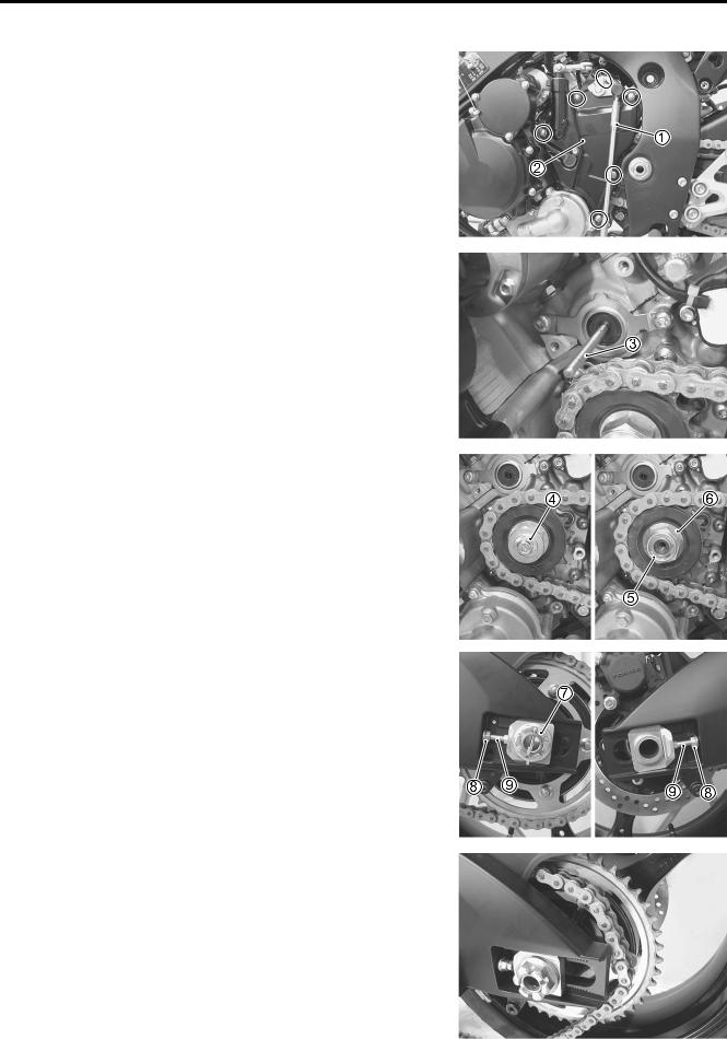
ENGINE SPROCKET AND GEARSHIFT LEVER
• Disengage the gearshift lever 1.
• Remove the engine sprocket cover 2.
• Remove the clutch push rod 3.
|
E |
• Remove the speed sensor rotor 4. |
L |
P |
|
• Remove the engine sprocket nut 5 and the washer 6. |
|
M |
|
A |
|
S |
|
•Remove the cotter pin. (For E-03, 28, 33)
•Loosen the rear axle nut 7.
•Loosen the chain adjuster lock-nuts 8.
•Loosen the chain adjusters 9.
•Push the rear wheel forward and make sure that the drive chain has enough slack.
•Disengage the drive chain from the rear sprocket.
3-8 ENGINE
• Remove the engine sprocket 0.
ENGINE MOUNTING
• Support the engine using an engine jack.
|
E |
• Remove the engine mounting bolt A. |
L |
|
P |
|
M |
A |
|
S |
|
•Loosen the engine mounting pinch bolt 1.
•Remove the engine mounting bolt B.

ENGINE 3-9
•Remove the engine mounting nut 2.
•Remove the engine mounting thrust adjuster lock-nut 3 with
the special tool.
• Loosen the engine mounting thrust adjuster 4 fully.
09940-14980: Engine mounting thrust adjuster socket wrench
|
|
|
|
E |
|
|
|
|
|
|
|
|
|
|
|
|
|
|
|
|
|
|
|
• Remove the engine mounting nut 5. |
L |
|
|||
|
|
|
P |
|
|
• Loosen the engine mounting thrust adjuster lock-nut 6 with |
|
||||
the special tool. |
|
|
|
|
|
• Loosen the engine mounting thrust adjuster 7 fully. |
|
||||
09940-14980: Engine mounting thrust adjuster |
|
||||
|
|
A |
|
||
|
socket wrench |
M |
|
||
NOTE: |
S |
|
|
|
|
|
|
|
|
|
|
Do not remove the engine mounting bolts at this stage.
•Remove the engine mounting bolts and gradually lower the front side of the engine. Then, take off the drive chain from the driveshaft.
•Remove the engine assembly.

3-10 ENGINE
ENGINE INSTALLATION
Install the engine in the reverse order of engine removal.
Pay attention to the following points:
NOTE:
Be careful not to damage the frame and engine when installing the engine.
• Before installing the engine, install the engine mounting thrust adjusters 1 and 2.
•Gradually raise the rear side of the engine assembly, and then put the drive chain on the driveshaft.
•Install all engine mounting bolts and tighten them temporarily.
( 3-11)
Be careful not to catch the wiring harness between the frame and the engine.
|
|
|
|
|
E |
• Tighten the engine mounting thrust adjusters to the specified |
L |
||||
torque. |
|
|
P |
||
09940-14980: Engine mounting thrust adjuster |
|||||
|
socket wrench |
M |
|
||
Engine mounting thrust adjuster: |
|
||||
|
A |
|
|
|
|
|
23 N·m (2.3 kgf-m, 16.5 lb-ft) |
|
|||
|
S |
|
|
|
|
• Tighten the engine mounting thrust adjuster lock-nuts to the |
|
||||
specified torque with the special tool.
09940-14980: Engine mounting thrust adjuster socket wrench
Engine mounting thrust adjuster lock-nut:
45N·m (4.5 kgf-m, 32.5 lb-ft)
•Tighten all engine mounting bolts and nuts to the specified torque. ( 3-11)
NOTE:
The engine mounting nuts are self-locking. Once the nuts have been removed, they are no longer of any use.
•Tighten the engine mounting pinch bolts to the specified torque. ( 3-11)

ENGINE 3-11
E |
L |
P |
M |
A |
S |
ITEM |
N·m |
kgf-m |
lb-ft |
|
|
|
|
AB |
55 |
5.5 |
40.0 |
|
|
|
|
1 |
23 |
2.3 |
16.5 |
|
|
|
|
34 |
23 |
2.3 |
16.5 |
|
|
|
|
56 |
45 |
4.5 |
32.5 |
|
|
|
|
78 |
75 |
7.5 |
54.0 |
LENGTH
ITEM |
|
mm |
in |
|
|
|
|
|
|
|
|
A |
45 |
1.77 |
|
|
|
|
|
Bolt |
|
B |
55 |
2.17 |
|
|
|
|
|
|
C |
215 |
8.46 |
|
|
|
|||
|
|
|
|
|
|
|
D |
205 |
8.07 |
|
|
|
|
|
Spacer |
|
2 |
30.5 |
1.20 |
|
|
|
|
|
Adjuster |
|
34 |
40 |
1.57 |
a Left b Right

3-12 ENGINE
•Install the engine sprocket and the washer.
•Apply a small quantity of THREAD LOCK to the driveshaft thread portion.
99000-32050: THREAD LOCK “1342”
• Tighten the engine sprocket nut to the specified torque.
Engine sprocket nut: 115 N·m (11.5 kgf-m, 83.0 lb-ft)
•Install the speed sensor rotor 3.
•Tighten the speed sensor rotor bolt 4 to the specified torque.
Speed sensor rotor bolt: 25 N·m (2.5 kgf-m, 18.0 lb-ft)
• Apply SUZUKI SUPER GREASE “A” to the clutch push rod |
E |
end. |
L |
99000-25010: SUZUKI SUPER GREASE “A” |
|
(or equivalent Pgrease) |
|
M |
|
• Install the engine sprocket cover. |
|
A |
|
S |
|
• Replace the exhaust pipe gaskets and muffler connector with |
|
new ones. |
|
NOTE: |
|
Be sure to face the tabs A on the exhaust pipe gaskets 5 to the |
|
exhaust pipe side when installing them. |
|

ENGINE 3-13
•Tighten the muffler mounting bolts, exhaust pipe bolts and muffler connecting bolt to the specified torque.
Muffler mounting bolt: 23 N·m (2.3 kgf-m, 16.5 lb-ft)
Muffler connecting bolt: 23 N·m (2.3 kgf-m, 16.5 lb-ft) Exhaust pipe bolt: 23 N·m (2.3 kgf-m, 16.5 lb-ft)
• Install the HO2 sensor 6. (For E-02, 19)
HO2 sensor: 48 N·m (4.8 kgf-m, 34.5 lb-ft)
|
|
E |
• Install the gearshift lever and adjust the lever height B. |
L |
|
Gearshift lever height B |
P |
|
|
|
|
Standard: 65 – 75 mm (2.56 – 2.95 in) |
|
|
M |
|
|
A |
|
|
S |
|
|
• Perform service and adjustment in the following items.
*Engine oil ( 2-12)
*Engine coolant ( 2-17)
*Throttle cable play ( 2-15)
*Clutch ( 2-16)
*Idling adjustment ( 2-14)
*Throttle valve synchronization ( 5-26)
*EXCV cable adjustment ( 6-8)
*Drive chain slack ( 2-21)
*Wiring harness, cables and hoses ( 10-17 to -24)