


7-6 COOLING AND LUBRICATION SYSTEM
COOLING FAN
REMOVAL
( 7-4)
INSPECTION
•Remove the right under cowling. ( 8-5)
•Disconnect the cooling fan coupler 1.
•Test the cooling fan motor for load current with an ammeter
connected as shown in the illustration.
• The voltmeter is for making sure that the battery 2 applies |
|
|
||
12 V to the cooling fan motor 3. With the cooling fan motor |
|
|
||
with electric motor fan running at full speed, the ammeter 4 |
|
|
||
should be indicating not 5 A and more. |
|
E |
||
• If the fan motor does not turn, replace the motor assembly |
|
|||
L |
||||
with a new one. |
|
|||
|
|
|
||
NOTE: |
P |
|||
|
||||
When making above test, it is not necessary to remove the cool- |
|
|
||
ing fan. |
M |
|
|
|
|
|
|
||
INSTALLATION |
A |
|
|
|
( 7-5) |
S |
|
|
|
|
|
|
||

COOLING AND LUBRICATION SYSTEM 7-7
COOLING FAN RELAY INSPECTION
Cooling fan relay is located on the air cleaner box (left side one).
• Lift and support the fuel tank. ( 8-3)
• Remove the cooling fan relay 1.
First check the insulation between A and B terminals with tester. Then apply 12 V to C and D terminals, + to C and - to D, and check the continuity between A and B.
If there is no continuity, replace it with a new one.
09900-25008: Multi-circuit tester set
Tester knob indication: Continuity test ( )
|
|
|
E |
|
|
|
L |
ECT SENSOR |
|
P |
|
REMOVAL |
|
M |
|
|
|
|
|
• Keep the motorcycle upright. |
|
|
|
|
A |
|
|
• Lift and support the fuel tank. ( 5-3) |
|
||
• Disconnect the ECT sensor coupler 1. |
|
||
• Place a rag under the ECT sensor and remove the ECT sen- |
|||
sor. |
S |
|
|
INSPECTION
•Check the ECT sensor by testing it at the bench as shown in the figure. Connect the ECT sensor 1 to a circuit tester and place it in the oil 2 contained in a pan, which is placed on a stove.
•Heat the oil to raise its temperature slowly and read the column thermometer 3 and the ohmmeter.

7-8 COOLING AND LUBRICATION SYSTEM
•If the ECT sensor ohmic value does not change in the proportion indicated, replace it with a new one.
Temperature sensor specification
Temperature |
Standard resistance |
|
|
20 °C (68 °F) |
Approx. 2.45 kΩ |
50 °C (122 °F) |
Approx. 0.811 kΩ |
80 °C (176 °F) |
Approx. 0.318 kΩ |
110 °C (230 °F) |
Approx. 0.142 kΩ |
Cooling fan operating temperature:
Standard (OFF→ON): Approx. 105 °C (221 °F) (ON→OFF): Approx. 100 °C (212 °F)
If the resistance is noted to show infinity or too much different |
E |
|||
resistance value, replace the ECT sensor with a new one. |
||||
|
|
|
|
|
|
|
|
|
|
* Take special care when handling the ECT sensor. It |
|
|||
|
L |
|||
may cause damage if it gets a sharp impact. |
|
|
||
* Do not contact the ECT sensor and the column ther- |
|
|
||
mometer with a pan. |
|
P |
||
M |
|
|
||
|
|
|
||
|
|
|||
|
A |
|
|
|
INSTALLATION S
• Tighten the ECT sensor to the specified torque.
ECT sensor: 18 N·m (1.8 kgf-m, 13.0 lb-ft)
Take special care when handling the ECT sensor. It may cause damage if it gets a sharp impact.
•Install the fuel tank. ( 5-4)
•Install the front seat.
•Pour engine coolant. ( 2-17)

COOLING AND LUBRICATION SYSTEM 7-9
THERMOSTAT
REMOVAL
•Drain engine coolant. ( 2-17)
•Lift and support the fuel tank. ( 5-3)
•Place a rag under the thermostat cover.
•Remove the thermostat cover 1.
•Remove the thermostat 2.
E
L
INSPECTION P
Inspect the thermostat pellet for signs ofMcracking.
Test the thermostat at the bench for control action, in the follow-
1A2
•Pass a string betweenSflange of thermostat, as shown.
•Immerse the thermostat in the water contained in a beaker, as shown in the illustration. Note that the immersed thermostat is in suspension. Heat the water 3 by placing the beaker on a stove 4 and observe the rising temperature on a thermometer 5.
•Read the thermometer just when opening the thermostat. This
reading, which is the temperature level at which the thermostat valve begins to open, should satisfy the standard value.ing manner.
Thermostat valve opening temperature
Standard: Approx. 82 °C (180 °F)
7-10 COOLING AND LUBRICATION SYSTEM
•Keep on heating the water to raise its temperature.
•Just when the water temperature reaches specified value, the
thermostat valve should have lifted by at least 8 mm (0.31 in).
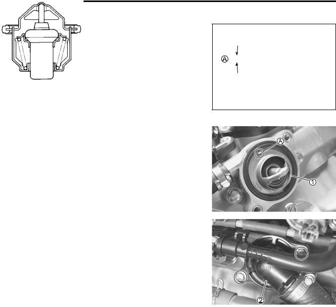
Thermostat valve lift A
Standard:
8.0mm and over at 95 °C (0.31 in and over at 203 °F)
•A thermostat failing to satisfy either of the two requirements (start-to-open temperature and valve lift) must be replaced.
INSTALLATION
• Install the thermostat 1.
NOTE:
The jiggle valve A of the thermostat faces upside.
|
E |
• Install the thermostat cover 2. |
L |
|
|
• Tighten the thermostat cover bolts to the specified torque. |
|
M |
|
Thermostat cover bolt: 10 N·m (1.0 kgf-m, 7.0 lb-ft)P |
|
A |
|
S |
|
•Install the fuel tank. ( 5-4)
•Install the front seat.
•Pour engine coolant. ( 2-17)