


8-18 CHASSIS
REMOVAL AND DISASSEMBLY
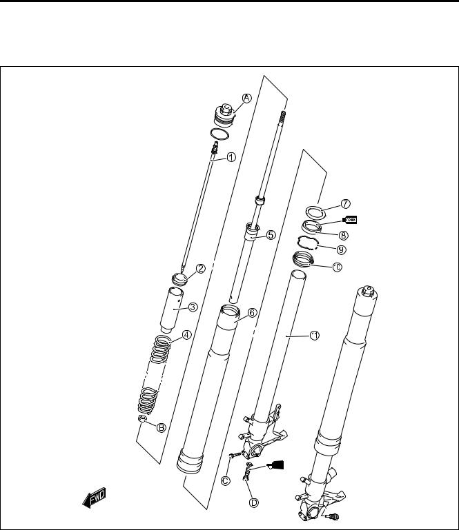
•Remove the under cowling cover and the lower bracket cover. ( 8-5)
•Remove the front wheel. ( 8-10)
•Disconnect the brake hose from the brake hose guides at the
front fender.
• Remove the front fender.
• Loosen the front fork upper clamp bolts 1, left and right. |
E |
|
• Loosen the handlebar clamp bolts 2, left and right. |
||
L |
||
NOTE: |
||
* Slightly loosen the front fork cap bolts 3 before looseningPthe |
||
lower clamp bolts to facilitate later disassembly. |
|
|
* Be sure to adjust the rebound damping forceMadjuster 4 to the |
|
|
softest position before removing the front fork. |
|
|
A |
|
|
S |
|
|
•Loosen the front fork lower clamp bolts, left and right.
•Remove the front forks, left and right.
NOTE:
Hold the front fork by the hand to prevent sliding out of the steering stem.
•Separate the front fork cap bolt from the front fork.
•Compress the front fork spring with the special tool A and insert the special tool B between the lock-nut and the spring retainer.
09940-94930: Front fork spacer holder A
09940-94922: Stopper plate B


8-20 CHASSIS
•Remove the damper rod bolt with the special tool and a hexagon wrench.
09940-30221: Front fork assembling tool
• Remove the inner rod/damper rod (cartridge) B.
Do not disassemble the inner rod/damper rod (cartridge).
|
|
E |
• Slide the outer tube to remove it from the inner tube. |
|
L |
NOTE: |
P |
|
|
|
|
Be careful not to damage the “ANTI-FRICTION” metals. |
|
|
M |
|
|
A |
|
|
S |
|
|
• Remove the dust seal C and oil seal stopper ring D.
CHASSIS 8-21
• Remove the oil seal E with the special tool.
09913-50121: Oil seal remover
The removed oil seal must be replaced with a new one.
• Remove the oil seal retainer F.
|
|
|
E |
|
|
L |
|
INSPECTION |
P |
||
|
|
||
INNER AND OUTER TUBES |
M |
||
|
|
||
|
• Inspect the inner tube outer surface and outer tube inner sur- |
||
|
face for scratches. |
A |
|
|
|
||
|
• Inspect the “ANTI-FRICTION” metal surfaces for scratches. |
||
|
• If any defects are found, replace them with the new ones. |
||
|
|
|
|
|
Do not remove theS“ANTI-FRICTION” metals, A and |
|
|
|
|
||
|
B. |
|
|
|
|
|
|
FORK SPRING
•Measure the fork spring free length.
•If it is shorter than the service limit, replace it with a new one.
Front fork spring free length A:
Service Limit: 241 mm (9.49 in)

8-22 CHASSIS
DAMPER ROD
•Move the inner rod by hand to examine it for smoothness.
•If any defects are found, replace inner rod/damper rod (cartridge) with a new one.
REASSEMBLY
Reassemble the front fork in the reverse order of disassembly.
Pay attention to the following points:
OIL SEAL AND DUST SEAL |
|
|
|
|
|
|
||
|
• Install the dust seal, oil seal stopper ring, oil seal and oil seal |
|
|
|
|
|||
|
retainer onto the inner tube. |
|
|
|
E |
|||
1 Dust seal |
|
|
|
|
||||
2 Oil seal stopper ring |
|
|
|
|
||||
|
|
|
L |
|||||
3 Oil seal |
|
|
|
|||||
|
|
|
|
|
|
|
||
4 Oil seal retainer |
|
|
|
|
|
|
|
|
|
|
|
|
|
|
|
|
|
|
* When installing the oil seal to outer tube, be carefulP |
|
|
|
||||
|
||||||||
|
|
|
|
|||||
|
not to damage the oil seal lip. |
A |
|
|
|
|
||
|
|
|
|
|
||||
|
|
|
|
|
|
|
||
|
* Avoid using solvents for washing to preventMoil seal |
|
|
|
|
|||
|
damage. |
S |
|
|
|
|
||
|
|
|
|
|
|
|
|
|
|
* Apply fork oil to the Anti-friction metals and lip of the |
|
|
|
|
|||
|
oil seal. |
|
|
|
|
|
|
|
|
|
|
|
|
|
|
|
|
|
* Make sure that the oil seal stopper ring has been fit- |
|
|
|
|
|||
|
|
|
|
|
||||
|
ted securely. |
|
|
|
|
|
|
|
|
|
|
|
|
|
|
|
|
• Insert the inner tube into the outer tube and fit the oil seal and dust seal with the special tool.
09940-52861: Front fork oil seal installer
NOTE:
Stamped mark on the oil seal should face outside.

CHASSIS 8-23
DAMPER ROD BOLT
•Insert the inner rod/damper rod (cartridge) into the inner tube.
•Apply THREAD LOCK to the damper rod bolt and tighten it to the specified torque with the special tool.
99000-32110: THREAD LOCK SUPER “1322”
(or equivalent thread lock)
Use a new damper rod bolt gasket 1 to prevent oil leakage.
09940-30221: Front fork assembling tool
Damper rod bolt: 35 N·m (3.5 kgf-m, 25.5 lb-ft)
|
|
E |
|
|
|
|
|
|
|
L |
|
COMPRESSION DAMPING FORCE ADJUSTER |
P |
|
|
|
|
||
• Tighten the compression damping force adjuster to the speci- |
|
||
fied torque. |
|
|
|
Compression damping force adjuster: |
|
|
|
|
A |
|
|
|
23 N·mM(2.3 kgf-m, 16.5 lb-ft) |
|
|
|
S |
|
|
|
|
|
|
The removed O-ring must be replaced with a new one.
FORK OIL
•Place the front fork vertically without spring.
•Compress it fully.
•Pour specified front fork oil up to the top level of the outer tube.
Capacity (each leg): 413 ml (14/14.5 US/lmp oz)
99000-99001-SS5: SUZUKI FORK OIL SS-05 or an equivalent fork oil

8-24 CHASSIS
•Move the inner rod slowly with the special tool ten times and more until no more bubbles come out from the oil.
09940-52841: Inner rod holder
NOTE:
Refill front fork oil up to the top of the outer tube so that bubbles are visible while bleeding air.
•Refill specified front fork oil up to the top level of the outer tube again. Move the outer tube up and down several strokes until no more bubbles come out from the oil.
•Keep the front fork vertically and wait 5 – 6 minutes.
NOTE: |
|
|
|
* Always keep oil level over the cartridge top end, or air may |
|
|
|
enter the cartridge during this procedure. |
|
|
|
* Take extreme care so as to pump out air completely. |
|
E |
|
|
|
|
|
• Hold the front fork vertically and adjust fork oil level with the |
L |
||
special tool. |
|
|
|
NOTE: |
M |
|
|
|
|
|
|
When adjusting the fork oil level, compress the outer tubePfully |
|||
without the fork spring. |
|
|
|
Fork oil level: 107 mm (4.21 in) |
|
|
|
S |
|
|
|
09943-74111: Front fork oil levelAgauge |
|
|
|
FORK SPRING
•Install the fork spring.
•Install the spring 1, spacer 2 and spring retainer 3.
FRONT FORK CAP BOLT
•Pull up the inner rod with the special tool A.
•Compress the spring with the special tool B and then insert the special tool C between the lock-nut and the spacer.
09940-52841: Inner rod holder A
09940-94930: Front fork spacer holder B
09940-94922: Stopper plate C

CHASSIS 8-25
•Insert the adjuster rod to the front fork cap bolt.
•Apply fork oil to the O-ring.
The removed O-ring must be replaced with a new one.
• Be sure to check or adjust the height D of the rebound damping force adjuster as follows.
H: 1.5 mm (0.05 in)
• Slowly turn the cap bolt completely by hand until the end of the cap bolt seats on the inner-rod.
• Apply fork oil to the O-ring.
|
|
|
E |
* The removed O-ring must be replaced with a new |
|
||
one. |
|
|
|
* Make sure that the rebound damping force adjuster |
|
||
1 to the softest position before installing the cap |
|
|
|
bolt. |
L |
||
P |
|
|
|
|
|
|
|
• Hold the cap bolt 2 and tighten the lock-nut 3 to the speci- |
|
||
fied torque. |
M |
|
|
A |
|
||
|
|
||
Inner rod lock-nut: 20 N·m (2.0 kgf-m, 14.5 lb-ft) |
|
||
|
S |
|
|
• Remove the special tools.
• Install the front fork cap bolt to the outer tube temporarily.

8-26 CHASSIS
INSTALLATION
Install the front fork in the reverse order of removal. Pay attention to the following points:
• Set the upper surface of the outer tube height A at 5.0 mm (0.196 in) from the upper surface of the steering stem upper bracket and tighten the front fork lower clamp bolts 1 to the specified torque.
Front fork lower clamp bolt: 23 N·m (2.3 kgf-m, 16.5 lb-ft)
•Tighten the front fork cap bolt 2 to the specified torque and recheck the front fork outer tube upper surface height A from the upper surface of the steering stem upper bracket.
Front fork cap bolt: 35 N·m (3.5 kgf-m, 25.5 lb-ft)
• Position the handlebars on the upper bracket.
( 8-37 to -38) |
|
|
• Tighten the front fork upper clamp bolts 3 and handlebar |
E |
|
clamp bolts 4. |
|
L |
|
P |
|
Front fork upper clamp bolt: 23 N·m (2.3 kgf-m, 16.5 lb-ft) |
|
|
Handlebar clamp bolt: 23 N·m (2.3 kgf-m, 16.5 lb-ft) |
|
|
• Remount the front wheel. ( 8-10) |
M |
|
• Cable routing ( 10-17) |
|
|
• Front brake hose routing ( 10-24)A |
|
|
S |
|
|

CHASSIS 8-27
SUSPENSION SETTING
After installing the front fork, adjust the spring pre-load and damping force as follows.
SPRING PRE-LOAD ADJUSTMENT
Turn the damping force adjuster 1 counterclockwise fully. It is at softest position and turn it out to standard setting position.
STD position: 7 turns in from softest position
DAMPING FORCE ADJUSTMENT Compression damping force
Turn the damping force adjuster 2 clockwise fully. It is at stiffest position and turn it out to standard setting position.pre-load.
STD position: 1 3/4 turns out from stiffest position |
E |
|
|
||
|
L |
|
|
P |
|
Rebound damping force |
M |
|
|
|
|
Turn the damping force adjuster 2 clockwise fully. It is at stiffest |
|
|
position and turn it out to standard setting position.pre-load. |
|
|
S |
|
|
STD position: 1 3/4 turnsAout from stiffest position |
|
|
STANDARD FRONT SUSPENSION SETTING
|
|
FRONT |
|
|
|
|
|
|
Spring pre-load |
Damping force adjuster |
|
|
adjuster |
Compression |
Rebound |
|
|
|
|
Solo and |
7 turns in from |
1 3/4 turns out from |
1 3/4 turns out from |
dual riding |
softest position |
stiffest position |
stiffest position |
Be sure to adjust the spring pre-load and damping force on both front fork legs equally.