


PERIODIC MAINTENANCE 2-1
PERIODIC MAINTENANCE
CONTENTS
PERIODIC MAINTENANCE SCHEDULE ....................................................
PERIODIC MAINTENANCE CHART.....................................................
LUBRICATION POINTS ........................................................................
MAINTENANCE AND TUNE-UP PROCEDURES .......................................
AIR CLEANER.......................................................................................
SPARK PLUG........................................................................................
VALVE CLEARANCE............................................................................
ENGINE OIL AND OIL FILTER .............................................................
EXHAUST CONTROL VALVE ..............................................................
FUEL LINE.............................................................................................
ENGINE IDLE SPEED |
........................................................................... |
|
|
|||
THROTTLE VALVE SYNCHRONIZATION ........................................... |
|
|||||
EVAPORATIVE EMISSION ..........CONTROL SYSTEM -33 ONLY) |
||||||
PAIR (AIR SUPPLY) SYSTEM .............................................................. |
|
(E |
||||
THROTTLE CABLE PLAY |
L |
|||||
P |
|
|||||
CLUTCH |
................................................................................................ |
|
|
|
||
COOLING SYSTEM |
|
|
||||
M |
|
|||||
DRIVE CHAIN |
|
|
||||
|
|
|
|
|||
BRAKE .................................................................................................. |
|
A |
|
|
||
TIRES |
|
|
|
|
||
..................................................................................................... |
|
|
|
|
|
|
STEERING............................................................................................. |
|
|
|
|
||
|
SU |
|
|
|
||
FRONT ........................................................................................FORK |
|
|
|
|
||
REAR ............................................................................ |
|
PEN ION |
|
|
|
|
EXHAUST .........................................................PIPE BOLT AND NUT |
|
|
||||
CHASSIS ..............................................................BOLTS AND NUTS |
|
|
||||
COMPRESSION PRESSURE CHECK ........................................................
COMPRESSION TEST PROCEDURE ..................................................
OIL PRESSURE CHECK .............................................................................
SDS CHECK.................................................................................................
2- |
2 |
|
|
|
2 |
||
2- |
2 |
|
|
2- |
3 |
|
|
|
|||
2- |
4 |
|
|
2- |
4 |
|
|
2- |
5 |
|
|
2- |
7 |
|
|
2-12 |
|
|
|
2-13 |
|
|
|
2-14 |
|
|
|
2-14 |
|
|
|
2-15 |
|
|
|
2-15 |
|
|
|
2-15 |
|
|
|
2-15 |
|
|
|
2-16 |
|
|
|
2-17 |
|
|
|
2-20 |
|
|
|
2-23 |
|
|
|
2-27 |
|
|
|
2-27 |
|
|
|
2-28 |
|
|
|
2-28 |
|
|
|
2-29 |
|
|
|
2-30 |
|
|
|
2-32 |
|
|
|
2-32 |
|
|
|
2-33 |
|
|
|
2-34 |
|
|
|
|
|
|
|

2-2 PERIODIC MAINTENANCE
PERIODIC MAINTENANCE SCHEDULE
The chart below lists the recommended intervals for all the required periodic service work necessary to keep the motorcycle operating at peak performance and economy. Mileages are expressed in terms of kilometers, miles and time for your convenience.
IMPORTANT (For E-28): The periodic maintenance intervals and service requirements have been established in accordance with EPA regulations. Following these instructions will ensure that the motorcycle will not exceed emission standards and it will also ensure the reliability and performance of the motorcycle.
NOTE:
More frequent servicing may be required on motorcycles that are used under severe conditions.
PERIODIC MAINTENANCE CHART
|
Interval |
miles |
600 |
4 000 |
|
7 500 |
11 000 |
14 500 |
|
|
km |
1 000 |
6 000 |
12 000 |
18 000 |
24 000 |
|
Item |
|
months |
2 |
12 |
|
24 |
36 |
48 |
Air cleaner element |
|
|
---- |
I |
|
I |
R |
I |
Spark plugs |
|
|
---- |
I |
|
R |
I |
R |
Valve clearance |
|
|
---- |
---- |
|
---- |
---- |
I |
Exhaust control valve |
|
|
I |
---- |
|
I |
---- |
I |
Engine oil |
|
|
R |
R |
|
R |
R |
R |
Engine oil filter |
|
|
R |
---- |
|
---- |
R |
---- |
|
|
|
|
|
E |
|
|
|
Fuel line |
|
|
---- |
I |
|
I |
I |
I |
Idle speed |
|
|
I |
L |
I |
I |
I |
|
|
|
I |
|
|||||
|
|
|
I |
|
|
|
|
|
Throttle valve synchronization |
|
P |
|
I |
---- |
I |
||
|
(E-33 only) |
---- |
|
|||||
Evaporative emission control system |
M |
---- |
|
I |
---- |
I |
||
|
|
|
||||||
(E-33 only) |
A |
---- |
|
|||||
|
|
|
|
|
|
|||
PAIR (air supply) system |
---- |
---- |
|
I |
---- |
I |
||
Throttle cable play |
S |
|
I |
I |
|
I |
I |
I |
Clutch cable play |
|
---- |
I |
|
I |
I |
I |
|
|
|
|
||||||
Radiator hoses |
|
|
---- |
I |
|
I |
I |
I |
Engine coolant |
|
|
|
Replace every 2 years. |
|
|||
Drive chain |
|
|
I |
I |
|
I |
I |
I |
|
|
|
Clean and lubricate every 1 000 km (600 miles). |
|||||
Brakes |
|
|
I |
I |
|
I |
I |
I |
|
|
|
---- |
I |
|
I |
I |
I |
Brake hoses |
|
|
|
|
|
|
Replace every 4 years. |
|
|||
|
|
|
|||
|
|
|
|
|
|
Brake fluid |
---- |
I |
I |
I |
I |
|
|
|
|
|
|
|
Replace every 2 years. |
|
|||
|
|
|
|||
|
|
|
|
|
|
Tires |
---- |
I |
I |
I |
I |
|
|
|
|
|
|
Steering |
I |
---- |
I |
---- |
I |
|
|
|
|
|
|
Front forks |
---- |
---- |
I |
---- |
I |
|
|
|
|
|
|
Rear suspension |
---- |
---- |
I |
---- |
I |
|
|
|
|
|
|
Exhaust pipe bolts and muffler bolt and nut |
T |
---- |
T |
---- |
T |
|
|
|
|
|
|
Chassis bolts and nuts |
T |
T |
T |
T |
T |
|
|
|
|
|
|
NOTE:
I = Inspect and clean, adjust, replace or lubricate as necessary; R = Replace; T = Tighten

PERIODIC MAINTENANCE 2-3
LUBRICATION POINTS
Proper lubrication is important for smooth operation and long life of each working part of the motorcycle. Major lubrication points are indicated below.
 Brake lever holder
Brake pedal pivot and footrestEpivot |
L |
P |
Clutch lever holder |
M |
A |
S |
Footrest pivot and |
Side-stand pivot |
Drive chain |
|
gearshift lever pivot |
|||
and spring hook |
|||
|
|
NOTE:
*Before lubricating each part, clean off any rusty spots and wipe off any grease, oil, dirt or grime.
*Lubricate exposed parts which are subject to rust, with a rust preventative spray whenever the motorcycle has been operated under wet or rainy conditions.
2-4 PERIODIC MAINTENANCE
MAINTENANCE AND TUNE-UP PROCEDURES
This section describes the servicing procedures for each item of the Periodic Maintenance requirements.
AIR CLEANER
Inspect every 6 000 km (4 000 miles, 12 months).
Replace every 18 000 km (11 000 miles, 36 months).
• Remove the front seat. ( 8-7)
• Lift and support the fuel tank. ( 5-3)
• Remove the air cleaner element by removing the screws.
• Remove the air cleaner element. |
|
|
|
||
• Inspect the air cleaner element for clogging. |
|
|
E |
||
If the air cleaner element is clogged with dust, replace the air |
|||||
|
|||||
cleaner element with a new one. |
|
|
|
||
|
|
|
|
|
|
|
|
|
|
||
|
P |
|
|||
Do not blow the air cleaner element with compressed |
L |
||||
air. |
M |
|
|
|
|
|
|
|
|
||
NOTE: |
|
|
|
||
A |
|
|
|
||
|
|
|
|
||
If driving under dusty conditions, replace the air cleaner element |
|
||||
more frequently. Make sure that the air cleaner is in good condi- |
|
||||
tion at all times. The life of the engine depends largely on this |
|
||||
component. |
S |
|
|
|
|
•Install a new air cleaner element in the reverse order of removal.
•Remove the drain plug from the air cleaner box to allow any water to drain out.

PERIODIC MAINTENANCE 2-5
SPARK PLUG
Inspect every 6 000 km (4 000 miles, 12 months).
Replace every 12 000 km (7 500 miles, 24 months).
SPARK PLUG AND IGNITION COIL/PLUG CAP REMOVAL
•Remove the front seat. ( 8-7)
•Lift and support the fuel tank. ( 5-3)
•Remove the air cleaner box. ( 5-14)
•Disconnect all lead wire couplers from ignition coil/plug caps.
Disconnect the lead wire coupler before removing the ignition coil/plug cap to avoid lead wire coupler damage.
• Remove the ignition coils/plug caps.
|
|
|
|
E |
* Do not pry up the ignition coil/plug cap with a screw |
|
|||
driver or a bar to avoid its damage. |
L |
|||
|
|
|
||
* Be careful not to drop the ignition coil/plug cap to |
|
|||
prevent short/open circuit. |
|
|
|
|
|
|
|
|
|
|
M |
|
|
|
• Remove the spark plugs with a spark plug wrench.P |
|
|||
HEAT RANGE |
|
|
|
|
• Check spark plug heat range by observing electrode color. If |
|
|||
S |
|
|
|
|
the electrode of the spark Aplug is wet appearing or dark color, |
|
|||
replace the spark plug with hotter type one. If it is white or |
|
|||
glazed appearing, replace the spark plug with colder type |
|
|||
one.
|
Hot type |
Standard |
Cold type |
|
|
|
|
NGK |
CR8E |
CR9E |
CR10E |
|
|
|
|
ND |
U24ESR-N |
U27ESR-N |
U31ESR-N |
NOTE:
“R” type spark plug has a resistor built into at the center electrode to prevent radio noise.
CARBON DEPOSITS
•Check carbon deposits on the spark plug.
•If carbon is deposited, remove it using a spark plug cleaner machine or carefully use a tool with a pointed end.

2-6 PERIODIC MAINTENANCE
SPARK PLUG GAP
•Measure the spark plug gap with a thickness gauge.
•Adjust the spark plug gap if necessary.
Spark plug gap:
Standard: 0.7 – 0.8 mm (0.028 – 0.031 in)
09900-20803: Thickness gauge
ELECTRODE’S CONDITION
•Check the condition of the electrode.
•If it is extremely worn or burnt, replace the spark plug. Replace the spark plug if it has a broken insulator, damaged thread, etc.
Confirm the thread size and reach when replacing the plug. If the reach is too short, carbon will be deposited on the screw portion of the plug hole and engine damage may result.
SPARK PLUG AND IGNITION COIL/PLUG CAP |
|
|
|
E |
|
INSTALLATION |
|
|
|
|
|
• Screw the spark plugs into the cylinder head with fingers, and |
|||||
then tighten them to the specified torque. |
|
L |
|||
Spark plug: 11 N·m (1.1 kgf-m, 8.0 Ib-ft) |
P |
|
|||
|
|
|
|||
M |
|
|
|
||
|
|
|
|
||
Do not cross thread or over tighten the spark plug, or |
|
|
|
||
such an operation will damage the aluminum threads |
|
|
|
||
of the cylinder head. |
A |
|
|
|
|
S |
|
|
|
|
|
|
|
|
|
|
|
•Install the ignition coils/plug caps and connect their lead wire couplers.
*Do not hit the ignition coil/plug cap with a plastic hammer when installing it.
*Place the ignition coil/spark plug cap so that the coupler does not touch the cylinder head cover.
CONTACT
INCORRECT INCORRECT

PERIODIC MAINTENANCE 2-7
VALVE CLEARANCE
Inspect every 24 000 km (14 500 miles, 48 months).
• Remove the right under cowling. ( 8-5)
• Lift and support the fuel tank. ( 5-3)
•Remove the air cleaner box. ( 5-14)
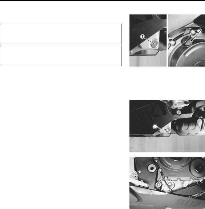
•Disconnect the CMP sensor coupler 1.
•Remove the PAIR control solenoid valve 2.
•Remove the spark plugs. ( 2-5)
•Loosen the throttle body clamp screws at the intake pipe side.
•Move the throttle body assembly.
•Move the radiator forward. ( 6-10)
•Remove the regulator/rectifier and horn. ( 3-6)
•Remove the cylinder head cover. ( 3-14)
|
|
|
E |
|
|
|
|
L |
|
||
The valve clearance specification is different for intake and |
|
|
|
||
exhaust valves. Valve clearance must be checked and adjusted, |
|
|
|
||
|
|
P |
|
|
|
1) at the time of periodic inspection, 2) when the valve mecha- |
|
|
|
||
nism is serviced, and 3) when the camshafts are removed for |
|
|
|
||
servicing. |
|
M |
|
|
|
|
A |
|
|
|
|
Valve clearance (when cold): |
|
|
|
|
|
Standard: IN. : 0.08 – 0.18 mm (0.003 – 0.007 in) |
|
|
|
||
|
EX. : 0.18 – 0.28 mm (0.007 – 0.011 in) |
|
|
|
|
NOTE: |
S |
|
|
|
|
|
|
|
|
||
* The cam must be at positions, A or B, when checking or |
|
|
|
||
adjusting the valve clearance. Clearance readings should not |
|
|
EX. IN. |
||
be taken with the cam in any other position than these two |
|
|
|
||
positions. |
|
|
|
|
|
*The clearance specification is for COLD state.
*To turn the crankshaft for clearance checking, be sure to use a wrench, and rotate in the normal running direction. All spark plugs should be removed.
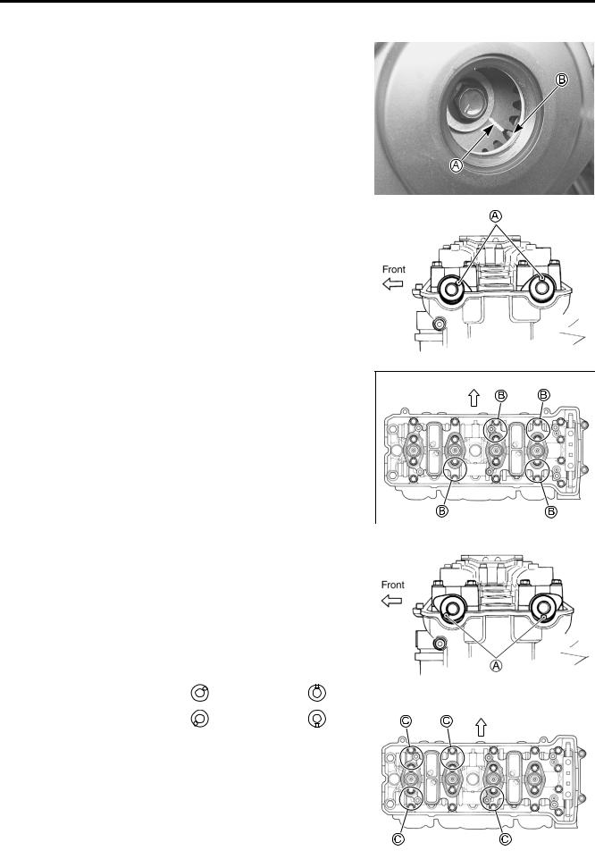
•Remove the valve timing inspection cap 1.
2-8 PERIODIC MAINTENANCE
•Turn the crankshaft to bring the line A on the CKP sensor rotor to the rib B behind the clutch cover and also to bring the
notches A on the left ends of both camshafts (Ex. and In.) to the positions as shown.
|
|
|
|
|
|
|
|
|
|
|
|
|
|
|
|
|
|
|
|
|
|
|
|
|
|
|
|
|
|
|
|
E |
|
|
|
|
|
|
|
|
|
|
||
|
|
|
L |
Front |
|
|
||
• In this condition, read the valve clearance at the valves B (In. |
|
|
|
|||||
and Ex. of No. 4 cylinder, Ex. of No. 3 and In. of No. 2). |
|
|
|
|
|
|
||
|
|
P |
|
|
|
|
||
• If the clearance is out of specification, adjust the clearance. |
|
|
|
|
|
|
||
( 2-9) |
|
M |
|
|
|
|
|
|
09900-20803: Thickness gauge |
|
|
|
|
|
|
||
|
A |
|
|
|
|
|
|
|
|
S |
|
|
|
|
|
|
|
|
|
|
|
|
|
|
|
|
|
|
|
|
|
|
|
|
|
• Turn the crankshaft 360 degrees (one rotation) to bring the |
|
|
|
|
||||
line on the CKP sensor rotor to the index mark of valve timing |
|
|
|
|
||||
inspection hole and also to bring the notches A to the posi- |
|
|
|
|
||||
tion as shown. |
|
|
|
|
|
|
|
|
• Read the clearance at the rest of the valves C and adjust the |
|
|
|
|
||||
clearance if necessary. ( 2-9) |
|
|
|
|
|
|
|
|
|
|
|
|
|
|
|
|
|
|
|
|
|
|
|
|
|
|
Cam position |
Notch A position |
|
|
|
|
|
|
|
|
|
|
|
|
|
|
|
|
Exhaust Camshaft |
Intake Camshaft |
|
|
|
|
|
|
|
|
|
|
|
|
|
|
||
|
|
|
|
|
|
|
|
|
B |
← Front |
← Front |
|
|
|
|
|
|
|
|
|
|
|
|
|||
C |
← Front |
← Front |
|
|
|
Front |
|
|
|
|
|
|
|
|
|||
|
|
|
|
|
|
|
|
|
|
|
|
|
|
|
|
|
|

PERIODIC MAINTENANCE 2-9
VALVE CLEARANCE ADJUSTMENT
The clearance is adjusted by replacing the existing tappet shim by a thicker or thinner shim.
•Remove the intake or exhaust camshafts. ( 3-14)
•Remove the tappet and shim by fingers or magnetic hand.
•Check the figures printed on the shim. These figures indicate the thickness of the shim, as illustrated.
•Select a replacement shim that will provide a clearance within the specified range. For the purpose of this adjustment, a total of 21 sizes of tappet shim are available ranging from 1.20 to 2.20 mm in steps of 0.05 mm. Fit the selected shim to the valve stem end, with numbers toward tappet. Be sure to
check shim size with micrometer to ensure its size. Refer to the tappet shim selection table ( 2-10 and -11) for details.
170 |
1.70 mm |
|
|
|
|
|
|
|
|
|
E |
|
|
|
|
|
|
|||
NOTE: |
L |
|
|
||
* Be sure to apply engine oil to tappet shim top and bottom |
|
|
|
|
|
faces. |
|
|
|
|
|
* When seating the tappet shim, be sure the figure printed sur- |
|
|
|
|
|
face faces the tappet. |
M |
|
|
|
|
P |
|
|
|
|
|
NOTE: |
|
|
|
|
|
Reinstall the camshafts in the specified manner. ( 3-92) |
|
|
|
|
|
S |
|
|
|
|
|
• After replacing the tappetAshim and camshafts, rotate the |
|
|
|
|
|
engine so that the tappet is depressed fully. This will squeeze |
|
|
|
|
|
|
|
|
|
||
out oil trapped between the shim and the tappet that could |
|
|
|
|
|
cause an incorrect measurement. Then check the clearance |
|
|
|
|
|
again to confirm that it is within the specified range. |
|
|
|
|
|
• After finishing the valve clearance adjustment, reinstall the following items.
*Cylinder head cover ( 3-97)
*Spark plug and plug cap ( 2-6)
*Throttle body assembly ( 5-21)
*Valve timing inspection plug ( 3-97)
*PAIR control solenoid valve ( 11-7)

TAPPET SHIM SELECTION TABLE [INTAKE]
TAPPET SHIM NO. (12892-05C00-XXX)
TAPPET SHIM SET (12800-05830)
|
SUFFIX |
120 |
125 |
130 |
135 |
S |
150 |
155 |
160 |
165 |
170 |
175 |
180 |
185 |
190 |
195 |
200 |
205 |
|
210 |
215 |
220 |
|
||
|
140 |
145 |
|
|
|||||||||||||||||||||
|
|
NO. |
|
|
|
|
|
|
|
|
|
|
|
|
|
|
|
|
|
|
|
|
|
|
|
MEASURED |
|
|
|
|
|
|
|
|
|
|
|
|
|
|
|
|
|
|
|
|
|
|
|
|
|
PRESENT |
|
|
|
|
|
|
|
|
|
|
|
|
|
|
|
|
|
|
|
|
|
|
|
||
VALVE |
|
|
|
|
|
A |
|
|
|
|
|
|
|
|
|
|
|
|
|
|
|
|
|||
SHIM SIZE |
|
|
|
|
|
|
|
|
|
|
|
|
|
|
|
|
|
|
|
|
|
||||
CLEARANCE |
|
|
|
|
|
|
|
|
|
|
|
|
|
|
|
|
|
|
|
|
|
||||
|
(mm) |
|
|
|
|
|
|
|
|
|
|
|
|
|
|
|
|
|
|
|
|
|
|||
(mm) |
|
1.20 |
1.25 |
1.30 |
1.35 |
1.40 |
1.45 |
1.50 |
1.55 |
1.60 |
1.65 |
1.70 |
1.75 |
1.80 |
1.85 |
1.90 |
1.95 |
2.00 |
2.05 |
|
2.10 |
2.15 |
2.20 |
|
|
|
|
|
|
|
|
|
|
|
|
|
|
|
|
|
|
|
|
|
|
|
|
|
|
|
|
0.00 – 0.04 |
|
|
|
|
1.20 |
1.25 |
1.30 |
1.35 |
1.40 |
1.45 |
1.50 |
1.55 |
1.60 |
1.65 |
1.70 |
1.75 |
1.80 |
1.85 |
1.90 |
1.95 |
|
2.00 |
2.05 |
2.10 |
|
|
|
|
|
|
|
|
|
|
|
|
|
|
|
|
|
|
|
|
|
|
|
|
|
|
|
0.05 – 0.09 |
|
|
|
1.20 |
1.25 |
1.30 |
1.35 |
1.40 |
1.45 |
1.50 |
1.55 |
1.60 |
1.65 |
1.70 |
1.75 |
1.80 |
1.85 |
1.90 |
1.95 |
2.00 |
|
2.05 |
2.10 |
2.15 |
|
|
|
|
|
|
|
|
|
|
|
|
|
|
|
|
|
|
|
|
|
|
|
|
|
|
|
0.10 – 0.20 |
|
|
|
|
|
|
|
|
M |
|
|
ADJUSTMENT REQUIRED |
|
|
|
|
|
|
|
|
|||||
|
|
|
|
|
|
|
|
SPECIFIED CLEARANCE/NO |
|
|
|
|
|
|
|
|
|||||||||
0.21 – 0.25 |
|
|
1.30 |
1.35 |
1.40 |
1.45 |
1.50 |
1.55 |
1.60 |
1.65 |
1.70 |
1.75 |
1.80 |
1.85 |
1.90 |
1.95 |
2.00 |
2.05 |
2.10 |
2.15 |
|
2.20 |
2.20 |
|
|
0.26 – 0.30 |
|
|
1.35 |
1.40 |
1.45 |
1.50 |
1.55 |
1.60 |
1.65 |
1.70 |
1.75 |
1.80 |
1.85 |
1.90 |
1.95 |
2.00 |
2.05 |
2.10 |
2.15 |
2.20 |
|
|
|
|
|
0.31 – 0.35 |
|
|
1.40 |
1.45 |
1.50 |
1.55 |
1.60 |
1.65 |
1.70 |
1.75 |
1.80 |
1.85 |
1.90 |
1.95 |
2.00 |
2.05 |
2.10 |
2.15 |
2.20 |
|
|
|
|
|
|
|
|
|
|
|
|
|
|
|
|
|
|
|
|
|
|
|
|
|
|
|
|
|
|
|
|
0.36 – 0.40 |
|
|
1.45 |
1.50 |
1.55 |
1.60 |
1.65 |
1.70 |
1.75 |
1.80 |
1.85 |
1.90 |
1.95 |
2.00 |
2.05 |
2.10 |
2.15 |
2.20 |
|
|
|
|
|
|
|
|
|
|
|
|
|
|
|
|
|
|
|
|
|
|
|
|
|
|
|
|
|
|
|
|
|
0.41 – 0.45 |
|
|
1.50 |
1.55 |
1.60 |
1.65 |
1.70 |
1.75 |
1.80 |
1.85 |
1.90 |
1.95 |
2.00 |
2.05 |
2.10 |
2.15 |
2.20 |
|
|
|
|
|
|
|
|
|
|
|
|
|
|
|
|
|
|
|
|
|
|
|
|
|
|
|
|
|
|
|
|
|
|
0.46 – 0.50 |
|
|
1.55 |
1.60 |
1.65 |
1.70 |
1.75 |
1.80 |
1.85 |
1.90 |
1.95 |
2.00 |
2.05 |
2.10 |
2.15 |
2.20 |
|
|
|
|
|
|
|
|
|
|
|
|
|
|
|
|
|
|
|
|
|
|
|
|
|
|
|
|
|
|
|
|
|
|
|
0.51 – 0.55 |
|
|
1.60 |
1.65 |
1.70 |
1.75 |
1.80 |
1.85 |
1.90 |
1.95 |
2.00 |
2.05 |
2.10 |
2.15 |
2.20 |
|
|
|
|
|
|
|
|
|
|
|
|
|
|
|
|
|
|
|
|
|
P |
|
|
|
|
|
|
|
|
|
|
|
|
|
|
0.56 – 0.60 |
|
|
1.65 |
1.70 |
1.75 |
1.80 |
1.85 |
1.90 |
1.95 |
2.00 |
2.05 2.10 |
2.15 |
2.20 |
|
|
|
|
|
|
|
|
|
|
|
|
|
|
|
|
|
|
|
|
|
|
|
|
|
|
|
|
|
|
|
|
|
|
|
|
|
|
0.61 – 0.65 |
|
|
1.70 |
1.75 |
1.80 |
1.85 |
1.90 |
1.95 |
2.00 |
2.05 |
2.10 |
2.15 |
2.20 |
|
|
|
|
|
|
|
|
|
|
|
|
|
|
|
|
|
|
|
|
|
|
|
|
|
|
|
|
|
|
|
|
|
|
|
|
|
|
0.66 – 0.70 |
|
|
1.75 |
1.80 |
1.85 |
1.90 |
1.95 |
2.00 |
2.05 |
2.10 |
2.15 |
2.20 |
E |
|
|
|
|
|
|
|
|
|
|
|
|
|
|
|
|
|
|
|
|
|
|
|
L |
|
|
|
|
|
|
|
|
|
|
|
|
||
0.71 – 0.75 |
|
|
1.80 |
1.85 |
1.90 |
1.95 |
2.00 |
2.05 |
2.10 |
2.15 |
2.20 |
|
|
|
|
|
|
|
|
|
|
|
|
|
|
|
|
|
|
|
|
|
|
|
|
|
|
|
|
|
|
|
|
|
|
|
|
|
|
|
|
0.76 – 0.80 |
|
|
1.85 |
1.90 |
1.95 |
2.00 |
2.05 |
2.10 |
2.15 |
2.20 |
|
|
|
|
|
|
|
|
|
|
|
|
|
|
|
|
|
|
|
|
|
|
|
|
|
|
|
|
|
|
|
|
|
|
|
|
|
|
|
|
|
0.81 – 0.85 |
|
|
1.90 |
1.95 |
2.00 |
2.05 |
2.10 |
2.15 |
2.20 |
|
|
|
|
|
|
|
|
|
|
|
|
|
|
|
|
|
|
|
|
|
|
|
|
|
|
|
|
|
|
|
|
|
|
|
|
|
|
|
|
|
|
0.86 – 0.90 |
|
|
1.95 |
2.00 |
2.05 |
2.10 |
2.15 |
2.20 |
|
|
|
|
|
|
|
|
|
|
|
|
|
|
|
|
|
|
|
|
|
|
|
|
|
|
|
|
|
|
|
|
|
|
|
|
|
|
|
|
|
|
|
0.91 – 0.95 |
|
|
2.00 |
2.05 |
2.10 |
2.15 |
2.20 |
|
|
|
|
HOW TO USE THIS CHART: |
|
|
|
|
|
|
|
|
|||||
|
|
|
|
|
|
|
|
|
|
|
|
|
|
|
|
|
|
|
|
||||||
0.96 – 1.00 |
|
|
2.05 |
2.10 |
2.15 |
2.20 |
|
|
|
|
|
|
|
|
|
|
|
|
|
||||||
|
|
|
|
|
|
|
|
|
|
|
|
I. |
Measure valve clearance. “ENGINE IS COLD” |
|
|
|
|
||||||||
1.01 – 1.05 |
|
|
2.10 |
2.15 |
2.20 |
|
|
|
|
|
|
|
|
|
|
||||||||||
|
|
|
|
|
|
|
|
II. |
Measure present shim size. |
|
|
|
|
|
|
|
|
||||||||
|
|
|
|
|
|
|
|
|
|
|
|
|
|
|
|
|
|
|
|
||||||
1.06 – 1.10 |
|
|
2.15 |
2.20 |
|
|
|
|
|
|
|
|
|
|
|
|
|
|
|
||||||
|
|
|
|
|
|
|
|
|
III. Match clearance in vertical column with present shim size in horizontal |
||||||||||||||||
|
|
|
|
|
|
|
|
|
|
|
|
||||||||||||||
1.11 – 1.15 |
|
|
2.20 |
|
|
|
|
|
|
|
|
||||||||||||||
|
|
|
|
|
|
|
|
|
|
|
column. |
|
|
|
|
|
|
|
|
|
|
|
|||
|
|
|
|
|
|
|
|
|
|
|
|
|
|
|
|
|
|
|
|
|
|
|
|
||
|
|
|
|
|
|
|
|
|
|
|
|
|
|
EXAMPLE |
|
|
|
|
|
|
|
|
|
||
|
|
|
|
|
|
|
|
|
|
|
|
|
Valve clearance is |
|
0.23 mm |
|
|
|
|
|
|
||||
|
|
|
|
|
|
|
|
|
|
|
|
|
Present shim size |
|
1.70 mm |
|
|
|
|
|
|
||||
|
|
|
|
|
|
|
|
|
|
|
|
|
Shim size to be used |
|
1.80 mm |
|
|
|
|
|
|
||||
SIDE)(INTAKE |
MAINTENANCE PERIODIC 10-2 |
|
|

TAPPET SHIM SELECTION TABLE [EXHAUST]
TAPPET SHIM NO. (12892-05C00-XXX)
TAPPET SHIM SET (12800-05830)
|
SUFFIX |
120 |
125 |
130 |
135 |
S |
150 |
155 |
160 |
165 |
170 |
175 |
180 |
185 |
190 |
195 |
200 |
205 |
|
210 |
215 |
220 |
|
||
|
140 |
145 |
|
|
|||||||||||||||||||||
|
|
NO. |
|
|
|
|
|
|
|
|
|
|
|
|
|
|
|
|
|
|
|
|
|
|
|
MEASURED |
|
|
|
|
|
|
|
|
|
|
|
|
|
|
|
|
|
|
|
|
|
|
|
|
|
PRESENT |
|
|
|
|
|
|
|
|
|
|
|
|
|
|
|
|
|
|
|
|
|
|
|
||
VALVE |
|
|
|
|
|
A |
|
|
|
|
|
|
|
|
|
|
|
|
|
|
|
|
|||
SHIM SIZE |
|
|
|
|
|
|
|
|
|
|
|
|
|
|
|
|
|
|
|
|
|
||||
CLEARANCE |
|
|
|
|
|
|
|
|
|
|
|
|
|
|
|
|
|
|
|
|
|
||||
|
(mm) |
|
|
|
|
|
|
|
|
|
|
|
|
|
|
|
|
|
|
|
|
|
|||
(mm) |
|
1.20 |
1.25 |
1.30 |
1.35 |
1.40 |
1.45 |
1.50 |
1.55 |
1.60 |
1.65 |
1.70 |
1.75 |
1.80 |
1.85 |
1.90 |
1.95 |
2.00 |
2.05 |
|
2.10 |
2.15 |
2.20 |
|
|
|
|
|
|
|
|
|
|
|
|
|
|
|
|
|
|
|
|
|
|
|
|
|
|
|
|
0.05 – 0.09 |
|
|
|
|
|
1.20 |
1.25 |
1.30 |
1.35 |
1.40 |
1.45 |
1.50 |
1.55 |
1.60 |
1.65 |
1.70 |
1.75 |
1.80 |
1.85 |
1.90 |
|
1.95 |
2.00 |
2.05 |
|
0.10 – 0.14 |
|
|
|
|
1.20 |
1.25 |
1.30 |
1.35 |
1.40 |
1.45 |
1.50 |
1.55 |
1.60 |
1.65 |
1.70 |
1.75 |
1.80 |
1.85 |
1.90 |
1.95 |
|
2.00 |
2.05 |
2.10 |
|
|
|
|
|
|
|
|
|
|
|
|
|
|
|
|
|
|
|
|
|
|
|
|
|
|
|
0.15 – 0.19 |
|
|
|
1.20 |
1.25 |
1.30 |
1.35 |
1.40 |
1.45 |
M |
1.55 |
1.60 |
1.65 |
1.70 |
1.75 |
1.80 |
1.85 |
1.90 |
1.95 |
2.00 |
2.05 |
2.10 |
2.15 |
|
|
|
|
|
1.50 |
|
|||||||||||||||||||||
0.20 – 0.30 |
|
|
|
|
|
|
|
|
SPECIFIED CLEARANCE/NO |
ADJUSTMENT REQUIRED |
|
|
|
|
|
|
|
|
|||||||
0.31 – 0.35 |
|
|
1.30 |
1.35 |
1.40 |
1.45 |
1.50 |
1.55 |
1.60 |
1.65 |
1.70 |
1.75 |
1.80 |
1.85 |
1.90 |
1.95 |
2.00 |
2.05 |
2.10 |
2.15 |
|
2.20 |
2.20 |
|
|
0.36 – 0.40 |
|
|
1.35 |
1.40 |
1.45 |
1.50 |
1.55 |
1.60 |
1.65 |
1.70 |
1.75 |
1.80 |
1.85 |
1.90 |
1.95 |
2.00 |
2.05 |
2.10 |
2.15 |
2.20 |
|
|
|
|
|
0.41 – 0.45 |
|
|
1.40 |
1.45 |
1.50 |
1.55 |
1.60 |
1.65 |
1.70 |
1.75 |
1.80 |
1.85 |
1.90 |
1.95 |
2.00 |
2.05 |
2.10 |
2.15 |
2.20 |
|
|
|
|
|
|
|
|
|
|
|
|
|
|
|
|
|
|
|
|
|
|
|
|
|
|
|
|
|
|
|
|
0.46 – 0.50 |
|
|
1.45 |
1.50 |
1.55 |
1.60 |
1.65 |
1.70 |
1.75 |
1.80 |
1.85 |
1.90 |
1.95 |
2.00 |
2.05 |
2.10 |
2.15 |
2.20 |
|
|
|
|
|
|
|
|
|
|
|
|
|
|
|
|
|
|
|
|
|
|
|
|
|
|
|
|
|
|
|
|
|
0.51 – 0.55 |
|
|
1.50 |
1.55 |
1.60 |
1.65 |
1.70 |
1.75 |
1.80 |
1.85 |
1.90 |
1.95 |
2.00 |
2.05 |
2.10 |
2.15 |
2.20 |
|
|
|
|
|
|
|
|
|
|
|
|
|
|
|
|
|
|
|
|
|
|
|
|
|
|
|
|
|
|
|
|
|
|
0.56 – 0.60 |
|
|
1.55 |
1.60 |
1.65 |
1.70 |
1.75 |
1.80 |
1.85 |
1.90 |
1.95 |
2.00 |
2.05 |
2.10 |
2.15 |
2.20 |
|
|
|
|
|
|
|
|
|
|
|
|
|
|
|
|
|
|
|
|
P |
|
|
|
|
|
|
|
|
|
|
|
|
|
|
0.61 – 0.65 |
|
|
1.60 |
1.65 |
1.70 |
1.75 |
1.80 |
1.85 |
1.90 |
1.95 |
2.00 2.05 |
2.10 |
2.15 |
2.20 |
|
|
|
|
|
|
|
|
|
|
|
|
|
|
|
|
|
|
|
|
|
|
|
|
|
|
|
|
|
|
|
|
|
|
|
|
|
0.66 – 0.70 |
|
|
1.65 |
1.70 |
1.75 |
1.80 |
1.85 |
1.90 |
1.95 |
2.00 |
2.05 |
2.10 |
2.15 |
2.20 |
|
|
|
|
|
|
|
|
|
|
|
|
|
|
|
|
|
|
|
|
|
|
|
|
|
|
|
|
|
|
|
|
|
|
|
|
|
0.71 – 0.75 |
|
|
1.70 |
1.75 |
1.80 |
1.85 |
1.90 |
1.95 |
2.00 |
2.05 |
2.10 |
2.15 |
E |
|
|
|
|
|
|
|
|
|
|
|
|
|
|
2.20 |
|
|
|
|
|
|
|
|
|
|
|
|
|||||||||||
|
|
|
|
|
|
|
|
|
|
|
L |
|
|
|
|
|
|
|
|
|
|
|
|
||
0.76 – 0.80 |
|
|
1.75 |
1.80 |
1.85 |
1.90 |
1.95 |
2.00 |
2.05 |
2.10 |
2.15 2.20 |
|
|
|
|
|
|
|
|
|
|
|
|
|
|
0.81 – 0.85 |
|
|
1.80 |
1.85 |
1.90 |
1.95 |
2.00 |
2.05 |
2.10 |
2.15 |
2.20 |
|
|
|
|
|
|
|
|
|
|
|
|
|
|
0.86 – 0.90 |
|
|
1.85 |
1.90 |
1.95 |
2.00 |
2.05 |
2.10 |
2.15 |
2.20 |
|
|
|
|
|
|
|
|
|
|
|
|
|
|
|
|
|
|
|
|
|
|
|
|
|
|
|
|
|
|
|
|
|
|
|
|
|
|
|
|
|
0.91 – 0.95 |
|
|
1.90 |
1.95 |
2.00 |
2.05 |
2.10 |
2.15 |
2.20 |
|
|
|
|
|
|
|
|
|
|
|
|
|
|
|
|
|
|
|
|
|
|
|
|
|
|
|
|
|
|
|
|
|
|
|
|
|
|
|
|
|
|
0.96 – 1.00 |
|
|
1.95 |
2.00 |
2.05 |
2.10 |
2.15 |
2.20 |
|
|
|
HOW TO USE THIS CHART: |
|
|
|
|
|
|
|
|
|||||
|
|
|
|
|
|
|
|
|
|
|
|
|
|
|
|
|
|
|
|
||||||
1.01 – 1.05 |
|
|
2.00 |
2.05 |
2.10 |
2.15 |
2.20 |
|
|
|
|
|
|
|
|
|
|
|
|
||||||
|
|
|
|
|
|
|
|
|
|
|
|
I. |
Measure valve clearance. “ENGINE IS COLD” |
|
|
|
|
||||||||
1.06 – 1.10 |
|
|
2.05 |
2.10 |
2.15 |
2.20 |
|
|
|
|
|
|
|
|
|
||||||||||
|
|
|
|
|
|
|
II. |
Measure present shim size. |
|
|
|
|
|
|
|
|
|||||||||
|
|
|
|
|
|
|
|
|
|
|
|
|
|
|
|
|
|
|
|
||||||
1.11 – 1.15 |
|
|
2.10 |
2.15 |
2.20 |
|
|
|
|
|
|
|
|
|
|
|
|
|
|
||||||
|
|
|
|
|
|
|
|
III. Match clearance in vertical column with present shim size in horizontal |
|||||||||||||||||
|
|
|
|
|
|
|
|
|
|
|
|
||||||||||||||
1.16 – 1.20 |
|
|
2.15 |
2.20 |
|
|
|
|
|
|
|
||||||||||||||
|
|
|
|
|
|
|
|
|
|
column. |
|
|
|
|
|
|
|
|
|
|
|
||||
|
|
|
|
|
|
|
|
|
|
|
|
|
|
|
|
|
|
|
|
|
|
|
|
||
1.21 – 1.25 |
|
|
2.20 |
|
|
|
|
|
|
|
|
|
|
|
|
|
|
|
|
|
|
|
|
||
|
|
|
|
|
|
|
|
|
|
|
|
EXAMPLE |
|
|
|
|
|
|
|
|
|
||||
|
|
|
|
|
|
|
|
|
|
|
|
|
|
|
|
|
|
|
|
|
|
|
|||
|
|
|
|
|
|
|
|
|
|
|
|
|
Valve clearance is |
|
0.33 mm |
|
|
|
|
|
|
||||
|
|
|
|
|
|
|
|
|
|
|
|
|
Present shim size |
|
1.70 mm |
|
|
|
|
|
|
||||
|
|
|
|
|
|
|
|
|
|
|
|
|
Shim size to be used |
|
1.80 mm |
|
|
|
|
|
|
||||
SIDE) (EXHAUST
11-2 MAINTENANCE PERIODIC
2-12 PERIODIC MAINTENANCE
Oil drain plug: 23 N·m (2.3 kgf-m, 16.5 lb-ft) |
E |
|
L |
|
P |
•Start up the engine and allow it to run forMseveral minutes at idling speed. A
•Turn off the engine andSwait about three minutes, then check the oil level through the inspection window. If the level is
below mark “L”, add oil to “F” level. If the level is above mark “F”, drain oil to “F” level.
F
 L
L


PERIODIC MAINTENANCE 2-13
OIL FILTER REPLACEMENT
• Drain the engine oil as described in the engine oil replacement procedure.
• Remove the oil filter 1 with the special tool.
09915-40610: Oil filter wrench
•Apply engine oil lightly to the gasket of the new oil filter before installation.
•Install the new oil filter. Turn it by hand until you feel that the
oil filter gasket contacts the oil filter mounting surface. Then, tighten the oil filter two full turns (or to specified torque) with the special tool.
NOTE: |
|
|
To properly tighten the oil filter, use the special tool. Never |
After contacting the |
|
tighten the oil filter by hand. |
||
gasket, tighten 2 turns. |
||
Oil filter: 20 N·m (2.0 kgf-m, 14.5 lb-ft) |
||
(20 N·m, 2.0 kgf-m, 14.5 lb-ft) |
|
|
|
|
|
|
|
|
E |
|
• Add new engine oil and check the oil level is as described in |
||||
the engine oil replacement procedure. |
L |
|||
|
|
|
||
NECESSARY AMOUNT OF ENGINE OIL: |
|
|
|
|
Oil change |
: 2.2 L (2.3/1.9 US/Imp qt) |
|
|
|
Oil and filter change |
M |
|
|
|
: 2.5 L (2.6/2.2 US/ImpPqt) |
|
|
||
Engine overhaul |
: 2.9 L (3.1/2.6 US/Imp qt) |
|
|
|
|
|
|
|
|
|
|
|
|
|
S |
|
|
|
|
ONLY USE A GENUINEAUZUKI MOTORCYCLE OIL |
|
|
||
FILTER. Other manufacturer’s oil filters may differ in |
|
|
||
thread specifications (thread diameter and pitch), fil- |
|
|
||
tering performance and durability which may lead to |
|
|
||
engine damage or oil leaks. Also, do not use a genuine |
|
|
||
Suzuki automobile oil filter on this motorcycle. |
|
|
|
|
|
|
|
|
|
EXHAUST CONTROL VALVE
Inspect initially at 1 000 km (600 miles, 2 months) and every 12 000 km (7 500 miles, 24 months) thereafter.
Exhaust control valve actuator is installed in the right-hand side in tail cowl.
Check the exhaust control valve actuator 1 for its movement when the ignition switch is turned ON. If the exhaust valve actuator does not move, check exhaust valve actuator electrical circuit and exhaust valve carbon sticking. Check the exhaust control cable play. ( 6-14)
2-14 PERIODIC MAINTENANCE
•Remove the under cowlings. ( 8-5)
•Check the lock-nuts tightness. If the lock-nuts are loose,
adjust the cable play and tighten the lock-nuts.
FUEL LINE
Inspect initially 6 000 km (4 000 miles, 12 months).
•Inspect the fuel feed hose 1 for damage and fuel leakage. If any defects are found, the fuel feed hose must be replaced.
|
|
|
E |
ENGINE IDLE SPEED |
L |
||
|
M |
|
|
Inspect initially at 1 000 km (600 miles, 2 months)Pand |
|||
every 6 000 km (4 000 miles, 12 months) thereafter. |
|
|
|
|
|
|
|
NOTE: |
A |
|
|
|
S |
|
|
Warm up the engine before adjusting the engine idle speed. |
|
|
|
• Start the engine, turn the throttle stop screw and set the engine idle speed as follows.
Engine idle speed: 1 300 ± 100 r/min
PERIODIC MAINTENANCE 2-15
THROTTLE VALVE SYNCHRONIZATION
Inspect initially at 1 000 km (600 miles, 2 months) (E-33 only) and every 12 000 km (7 500 miles, 24 moths).
•Inspect the throttle valve synchronization periodically. ( 5-26)
EVAPORATIVE EMISSION CONTROL
SYSTEM (E-33 ONLY)
Inspect every 12 000 km (7 500 miles, 24 months).
Replace vapor hose every 4 years.
• Inspect the evaporative emission control system periodically.
PAIR (AIR SUPPLY) SYSTEM
Inspect every 12 000 km (7 500 miles, 24 months). |
E |
||
|
|||
|
|
|
|
|
|
L |
|
• Inspect the PAIR (air supply) system periodically. ( 11-6) |
|
||
THROTTLE CABLE PLAY |
|
P |
|
M |
|
||
|
|
||
|
|
||
A |
|
|
|
Inspect initially at 1 000 km (600 miles, 2 months) and |
|
||
every 6 000 km (4 000 miles, 12 months) thereafter. |
|
||
S |
|
|
|
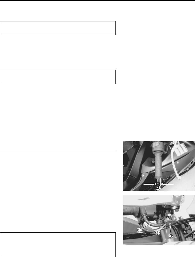
• Adjust the throttle cable play A as follows. |
|
|
|
• Loosen the lock-nut 2 of the throttle pulling cable 1.
• Turn the adjuster 3 in or out until the throttle cable play (at the throttle grip) A is between 2.0 – 4.0 mm (0.08 – 0.16 in).
• Tighten the lock-nut 2 while holding the adjuster 3.
Throttle cable play A: 2.0 – 4.0 mm (0.08 – 0.16 in)
After the adjustment is completed, check that handlebar movement does not raise the engine idle speed and that the throttle grip returns smoothly and automatically.

2-16 PERIODIC MAINTENANCE
CLUTCH
Inspect every 6 000 km (4 000 miles, 12 months).
•Lift and support the fuel tank with its prop stay. ( 5-3)
•Turn in the adjuster 1 all the way into the clutch lever assembly.
•Loosen the lock-nut 2 and turn the clutch cable adjuster 3 to obtain proper cable play.
|
|
|
E |
• Remove the clutch release adjuster cap. |
L |
||
|
|
||
• Loosen the lock-nut 4 and turn out the adjusting screw 5 |
|
||
two or three rotations. |
|
|
|
• From that position, slowly turn in the adjusting screw 5 until |
|
||
resistance is felt. |
|
P |
|
• From this position, turn out the adjusting screw 5 1/2 rotation, |
|
||
|
A |
|
|
and tighten the lock-nut 4 while holding Mthe screw 5. |
|
||
S |
|
|
|
• Turn the cable adjuster |
3 to obtain 10 – 15 mm (0.4 – 0.6 in) |
|
|
of free play A at the clutch lever end.
• Tighten the lock-nut 2.
Clutch lever play A: 10 – 15 mm (0.4 – 0.6 in)
Clutch release screw: 1/2 turn out
Clutch release adjuster cap: 11 N·m (1.1 kgf-m, 8.0 lb-ft)

PERIODIC MAINTENANCE 2-17
COOLING SYSTEM
Inspect every 6 000 km (4 000 miles, 12 months).
Replace engine coolant every 2 years.
ENGINE COOLANT LEVEL CHECK
•Keep the motorcycle upright.
•Check the engine coolant level by observing the full and lower lines on the engine coolant reservoir.
A Full line B Lower line
•If the level is below the lower line, remove the right under cowling ( 8-5), and add engine coolant to the full line from
the engine coolant reservoir filler.
ENGINE COOLANT CHANGE |
|
|
|
E |
||
• Remove the under cowlings. ( 8-5) |
|
|
||||
L |
||||||
• Remove the radiator cap 1. |
|
|||||
|
|
|
||||
• Drain engine coolant by disconnecting the radiator hose 2 |
|
|||||
from the pump. |
|
|
P |
|
||
|
M |
|
|
|||
|
|
|
|
|||
|
|
|
|
|||
|
A |
|
|
|
||
*Do not open the radiator
comes in contact with skin or eyes. If engine coolant gets into the eyes or in contact with the skin, flush thoroughly with plenty of water. If swallowed, induce vomiting and call physician immediately!
•Flush the radiator with fresh water if necessary.
•Connect the radiator hose 2 securely.
•Pour the specified engine coolant up to the radiator inlet.cap when the engine is hot,as you may beSinjured by escaping hot liquid orvapor.* Engine coolant may be harmful if swallowed or if it
Engine coolant capacity (excluding reservoir):
2 400 ml (2.5/2.1 US/lmp qt)
•Bleed the air from the engine coolant circuit in the following procedure. ( 2-18)
ENGINE COOLANT INFORMATION ( 7-2)

2-18 PERIODIC MAINTENANCE
AIR BLEEDING THE COOLING CIRCUIT
•Add engine coolant up to the radiator inlet.
•Support the motorcycle upright.
•Slowly swing the motorcycle, right and left, to bleed the air trapped in the cooling circuit.
•Add engine coolant up to the radiator inlet.
•Start up the engine and bleed air from the radiator inlet completely.
•Add engine coolant up to the radiator inlet.
• Repeat the above procedure until no air bleeds from the radiator inlet.
• Loosen the air bleeding bolt 1 and check that the engine coolant flows out.
• Close the air bleeding bolt securely. |
|
|
|
||
• Close the radiator cap securely. |
|
L |
|||
|
|
|
|||
• After warming up and cooling down the engine several times, |
E |
||||
|
|
P |
|
||
add the engine coolant up to the full level of the reservoir. |
|
|
|
||
|
|
|
|
|
|
|
|
M |
|
|
|
Repeat the above procedure several times and make |
|
|
|
||
|
|
A |
|
|
|
sure that the radiator is filled with engine coolant up to |
|
|
|
||
the reservoir full level. |
|
|
|
|
|
Engine coolant capacity: |
|
|
|
|
|
Engine side |
S: 2 400 ml (2.5/2.1 US/Imp qt) |
|
|
|
|
Reservoir tank side : 250 ml (0.3/0.2 US/lmp qt)

PERIODIC MAINTENANCE 2-19
RADIATOR HOSES
•Remove the under cowlings. ( 8-5)
•Lift and support the fuel tank. ( 5-3)
•Check the radiator hoses for crack, damage or engine coolant leakage.
•If any defect is found, replace the radiator hose with new one.
E
L
P
M
A
S
2-20 PERIODIC MAINTENANCE
DRIVE CHAIN
Inspect initially at 1 000 km (600 miles, 2 months) and every 6 000 km (4 000 miles, 12 months) thereafter. Clean and lubricate every 1 000 km (600 miles).
Visually check the drive chain for the possible defects listed below. (Support the motorcycle by a jack and a wooden block, turn the rear wheel slowly by hand with the transmission shifted to Neutral.)
* Loose pins |
* Excessive wear |
* Damaged rollers |
* Improper chain adjustment |
* Dry or rusted links |
* Missing O-ring seals |
* Kinked or binding links |
|
If any defect is found, the drive chain must be replaced.
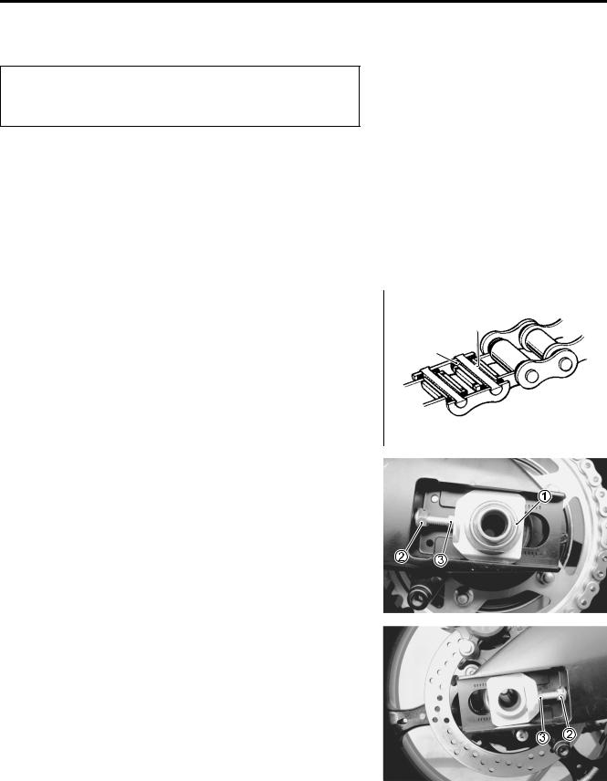
NOTE: |
|
|
When replacing the drive chain, replace the drive chain and |
Grease |
|
sprockets as a set. |
|
|
|
|
|
|
|
O-ring |
|
|
E |
|
L |
|
|
P |
|
|
|
|
CHECKING |
M |
|
|
A |
|
• Remove the axle cotter pin. (For E-03, 28, 33) |
||
• Loosen the axle nut 1. |
S |
|
|
||
• Loosen the chain adjuster lock-nuts 2.
• Give tension to the drive chain fully by turning both chain adjuster bolts 3.

PERIODIC MAINTENANCE 2-21
• Count out 21 pins (20 pitches) on the chain and measure the |
|
|
distance between the two points. If the distance exceeds the |
1 2 3 |
1920 21 |
service limit, the chain must be replaced. |
|
|
Drive chain 20-pitch length:
Service limit: 319.4 mm (12.57 in)
ADJUSTING
•Loosen or tighten both chain adjuster bolts 1 until there is 20
– 30 mm (0.8 – 1.2 in) of slack at the middle of the chain between the engine and rear sprockets as shown. The chain adjuster position relative to the reference marks A on both
sides of the swingarm must be equal to ensure that the front |
|
|
|
||
and rear wheels are correctly aligned. |
|
|
|
|
20 – 30 mm |
Drive chain slack: |
|
|
|
|
(0.8 – 1.2 in) |
|
|
|
|
|
|
Standard: 20 – 30 mm (0.8 – 1.2 in) |
|
|
|
|
|
• Place the motorcycle on its side-stand for accurate adjust- |
E |
|
|||
ment. |
|
|
|
||
|
|
|
|
|
|
• After adjusting the drive chain, tighten the axle nut 2 to the |
|
|
|
||
specified torque. |
|
L |
|
||
P |
|
|
|
||
|
|
|
|
||
• Tighten both chain adjuster lock-nuts 3 securely. |
|
|
|
|
|
Rear axle nut: 100 N·m (10.0 kgf-m, 72.5 lb-ft) |
|
|
|
|
|
M |
|
|
|
|
|
• Install a new cotter pin. (For E-03, 28, 33) |
|
|
|
|
|
• Recheck the drive chain slackAafter tightening the axle nut. |
|
|
|
||
S |
|
|
|
|
|
NOTE:
Do not adjust the drive chain beyond the adjustable range A.
Replace the drive chain before drive chain exceeds the limit.

2-22 PERIODIC MAINTENANCE
CLEANING AND LUBRICATING
•Clean the drive chain with kerosine. If the drive chain tends to rust quickly, the intervals must be shortened.
Do not use trichloroethylene, gasoline or any similar solvent. These fluids will damage the O-rings. Use only kerosine to clean the drive chain.
•After washing and drying the chain, oil it with a heavyweight motor oil.
*Do not use any oil sold commercially as “drive chain oil”. Such oil can damage the O-rings.
* The standard drive chain is RK525SMOZ7Y. Suzuki recommends to use this standard drive chain as a replacement.
E
L
P
M
A
S

PERIODIC MAINTENANCE 2-23
BRAKE
(BRAKE)
Inspect initially at 1 000 km (600 miles, 2 months) and every 6 000 km (4 000 miles, 12 months) thereafter.
(BRAKE HOSE AND BRAKE FLUID)
Inspect every 6 000 km (4 000 miles, 12 months). Replace hoses every 4 years. Replace fluid every 2 years.
BRAKE FLUID LEVEL CHECK
•Keep the motorcycle upright and place the handlebars straight.
•Check the brake fluid level relative to the lower limit lines on the front and rear brake fluid reservoirs.
•When the level is below the lower limit line, replenish with brake fluid that meets the following specification.
|
Specification and classification: DOT 4 |
|
E |
|
|
||
|
L |
||
|
|
||
|
|
||
|
* The brake system of this motorcycle is filled with a |
|
|
|
|
P |
|
|
glycol-based brake fluid. Do not use or mix different |
|
|
|
types of fluid such as silicone-based and petro- |
|
|
|
M |
|
|
|
leum-based fluids. Do not use any brake fluid taken |
|
|
|
A |
|
|
|
from old, used or unsealed containers. Never re-use |
|
|
|
brake fluid left over from the last servicing or stored |
|
|
|
S |
|
|
|
for a long period of time. |
|
|
|
* Brake fluid, if it leaks, will interfere with safe running |
|
|
|
and immediately discolor painted surfaces. Check |
|
|
|
the brake hoses and hose joints for cracks and fluid |
|
|
|
leakage before riding. |
|
|
|
|
|
|
F

L

 F
F
 L
L
2-24 PERIODIC MAINTENANCE
BRAKE PADS Front brake
The extent of brake pad wear can be checked by observing the grooved limit line A on the pad. When the wear exceeds the grooved limit line, replace the pads with the new ones.
( 8-65)
Replace the brake pads as a set, otherwise braking performance will be adversely affected.
|
|
|
|
|
|
|
|
|
|
|
|
|
|
|
|
|
|
|
|
|
|
|
|
|
|
|
|
|
|
|
|
|
|
|
Rear brake |
|
|
E |
|
|
|
|
|
|
|
|||
|
|
|
|
|
|
|
The extent of brake pad wear can be checked by observing the |
|
|
|
|
||
|
P |
|
|
|
|
|
grooved limit line B on the pad. When the wear exceeds theL |
|
|
||||
grooved limit line, replace the pads with the new ones. |
|
|
|
|
||
( 8-76) |
M |
|
|
|
|
|
|
A |
|
|
|
|
|
|
|
|
|
|
|
|
|
S |
|
|
|
|
|
Replace the brake pads as a set, otherwise braking |
|
|
|
|
|
|
performance will be adversely affected. |
|
|
|
|
|
|
|
|
|
|
|
|
|
|
|
|
|
|
|
|
BRAKE PEDAL HEIGHT
•Loosen the lock-nut 1.
•Turn the push rod 2 until the brake pedal height becomes 65
– 75 mm (2.6 – 3.0 in) A below the top of the footrest.
•Tighten the lock-nut 1 securely.
Rear brake master cylinder rod lock-nut:
18 N·m (1.8 kgf-m, 13.0 Ib-ft)
Brake pedal height A:
Standard: 65 – 75 mm (2.6 – 3.0 in)

PERIODIC MAINTENANCE 2-25

2-26 PERIODIC MAINTENANCE
FRONT BRAKE (Master cylinder side)
•Bleed air from the master cylinder in the same manner as front brake (caliper side).
Air bleeder valve: 6.0 N·m (0.6 kgf-m, 4.3 Ib-ft)
NOTE:
If air is trapped in the master cylinder, bleed air from the master cylinder first.
REAR BRAKE
•Bleed air from the rear brake system in the same manner as front brake.
Air bleeder valve: 7.5 N·m (0.75 kgf-m, 5.5 Ib-ft)
NOTE:
The only of between operation from bleeding the front brake is that the rear master cylinder is actuated by a pedal.
E
L
P
M
A
S
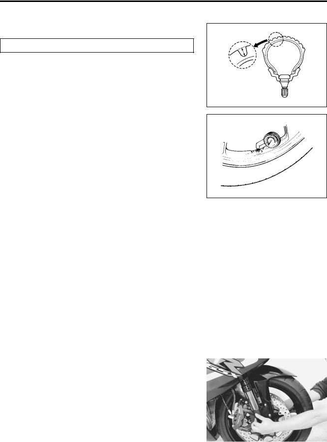
PERIODIC MAINTENANCE 2-27
09900-20805: Tire depth gauge
Tire tread depth:
Service Limit: FRONT : 1.6 mm (0.06 in) REAR : 2.0 mm (0.08 in)
TIRE PRESSURE
If the tire pressure is too high or too low, steering will be adversely affected and tire wear will increase. Therefore, maintain the correct tire pressure for good roadability and a longer tire life. Cold inflation tire pressure is as follows.
Cold inflation tire pressure
|
2 |
|
|
E |
|
Solo riding: Front: 250 kPa (2.50 kgf/cm |
, 36 psi) |
||||
|
|||||
Rear: |
250 kPa (2.50 kgf/cm2, 36 psi) |
|
|||
Dual riding: Front: |
|
L |
|||
250 kPa (2.50 kgf/cm2, 36 psi) |
|
||||
Rear: |
2 |
|
|
|
|
290 kPa (2.90 kgf/cmP, 42 psi) |
|
||||
|
M |
|
|
||
|
|
|
|||
The standard tire fitted on this motorcycle is 120/70 |
|
|
|||
ZR17 M/C (58 W) for the Afront and 180/55 ZR17 M/C (73 |
|
|
|||
W) for the rear. The use of tires other than those spec- |
|
|
|||
S |
|
|
|
||
ified may cause instability. It is highly recommended |
|
|
|||
to use the specified tires. |
|
|
|
||
|
|
|
|
|
|
TIRE TYPE |
|
|
|
|
|
BRIDGESTONE (Front: BT014FJ, Rear: BT014R N) |
|
||||
STEERING |
|
|
|
|
|
|
|
||||
Inspect initially at 1 000 km (600 miles, 2 months) and |
|
|
|||
every 12 000 km (7 500 miles, 24 months) thereafter. |
|
|
|||
|
|
|
|||
The steering should be adjusted properly for smooth turning of |
|
||||
the handlebars and safe operation. Overtighten steering pre- |
|
||||
vents smooth turning of the handlebars and too loose steering |
|
||||
will cause poor stability. Check that there is no play in the front |
|
||||
fork. Support the motorcycle so that the front wheel is off the |
|
||||
ground. With the wheel facing straight ahead, grasp the lower |
|
||||
fork tubes near the axle and pull forward. If play is found, read- |
|
||||
just the steering. ( 8-33) |
|
|
|
|
|

2-28 PERIODIC MAINTENANCE
FRONT FORK
Inspect every 12 000 km (7 500 miles, 24 months).
•Inspect the front forks for oil leakage, scoring or scratches on
the outer surface of the inner tubes. Replace any defective parts, if necessary. ( 8-18)
REAR SUSPENSION
Inspect every 12 000 km (7 500 miles, 24 months).
•Inspect the rear shock absorbers for oil leakage and check
that there is no play in the swingarm. Replace any defective parts if necessary. ( 8-49)
E
L
P
M
A
S
PERIODIC MAINTENANCE 2-29
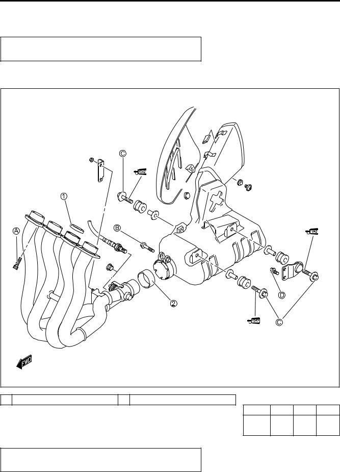
EXHAUST PIPE BOLT AND NUT
Tighten initially at 1 000 km (600 miles, 2 months) and every 12 000 km (7 500 miles, 24 months) thereafter.
•Tighten the exhaust pipe bolts, muffler mounting bolt and nut to the specified torque.
|
E |
|
|
|
|
|
L |
|
|
|
|
|
P |
|
|
|
|
|
M |
|
|
|
|
|
A |
|
|
|
|
|
S |
|
|
|
|
1 Gasket |
2 Exhaust pipe connecter |
|
|
|
|
|
|
ITEM |
N·m |
kgf-m |
lb-ft |
|
|
AB |
23 |
2.3 |
16.5 |
|
|
CD |
|||
|
|
|
|
|
|
|
|
|
|
|
|
Replace the gaskets and exhaust pipe connector with |
|
|
|
|
|
the new ones. |
|
|
|
|
|

2-30 PERIODIC MAINTENANCE
CHASSIS BOLTS AND NUTS
Tighten initially at 1 000 km (600 miles, 2 months) and every 6 000 km (4 000 miles, 12 months) thereafter.
Check that all chassis bolts and nuts are tightened to their specified torque. (Refer to page 2-31 for the locations of the following nuts and bolts on the motorcycle.)
Item |
|
|
|
N·m |
|
kgf-m |
Ib-ft |
|
|
|
|
|
|
|
|
1 Steering stem head nut |
|
|
|
90 |
|
9.0 |
65.0 |
|
|
|
|
|
|
|
|
2 Steering stem lock-nut |
|
|
|
80 |
|
8.0 |
58.0 |
|
|
|
|
|
|
|
|
3 Front fork upper clamp bolt |
|
|
|
23 |
|
2.3 |
16.5 |
|
|
|
|
|
|
|
|
4 Front fork lower clamp bolt |
|
|
|
23 |
|
2.3 |
16.5 |
|
|
|
|
|
|
|
|
5 Front fork cap bolt |
|
|
|
23 |
|
2.3 |
16.5 |
|
|
|
|
|
|
|
|
6 Front axle bolt |
|
|
|
100 |
|
10.0 |
72.5 |
|
|
|
|
|
|
|
|
7 Front axle pinch bolt |
|
|
|
23 |
|
2.3 |
16.5 |
|
|
|
|
|
|
|
|
8 Handlebar clamp bolt |
|
|
|
23 |
|
2.3 |
16.5 |
|
|
|
|
|
|
||
9 Front brake master cylinder mounting bolt |
|
10 |
|
1.0 |
7.0 |
||
|
|
|
|
|
|
|
|
0 Front brake caliper mounting bolt |
|
|
39 |
|
3.9 |
28.0 |
|
|
|
|
|
|
|
|
|
A Front brake caliper housing bolt |
|
|
22 |
|
2.2 |
16.0 |
|
|
|
|
|
|
|
|
|
B Brake hose union bolt (Front & Rear) |
|
|
23 |
|
2.3 |
16.5 |
|
|
|
|
|
|
E |
|
|
C Air bleeder valve |
|
|
|
7.5 |
|
5.5 |
|
(Front brake caliper & Rear brake caliper) |
|
|
0.75 |
||||
|
L |
|
|
||||
|
|
|
|
|
|
||
D Air bleeder valve (Master cylinder) |
|
|
6.0 |
|
0.6 |
4.5 |
|
|
|
|
P |
|
|
|
|
E Brake disc bolt (Front) |
|
|
|
23 |
|
2.3 |
16.5 |
|
|
|
|
|
|
|
|
F Brake disc bolt (Rear) |
|
M |
35 |
|
3.5 |
25.5 |
|
|
|
|
|
|
|
||
G Rear brake caliper mounting bolt |
|
|
17 |
|
1.7 |
12.5 |
|
|
|
|
|
|
|
||
H Rear brake master cylinder mounting bolt |
|
10 |
|
1.0 |
7.0 |
||
|
A |
|
|
|
|
|
|
I Rear brake master cylinder rod lock-nut |
|
|
18 |
|
1.8 |
13.0 |
|
S |
|
|
|
|
|
|
|
J Front footrest bracket mounting bolt |
|
|
23 |
|
2.3 |
16.5 |
|
|
|
|
|
|
|
|
|
K Swingarm pivot nut |
|
|
|
100 |
|
10.0 |
72.5 |
|
|
|
|
|
|
|
|
L Swingarm pivot lock-nut |
|
|
|
90 |
|
9.0 |
65.0 |
|
|
|
|
|
|
|
|
M Rear suspension bracket nut |
|
|
|
115 |
|
11.5 |
83.0 |
|
|
|
|
|
|||
N Rear shock absorber mounting bolt/nut (Upper & Lower) |
50 |
|
5.0 |
36.0 |
|||
|
|
|
|
|
|
|
|
O Cushion rod nut |
|
|
|
78 |
|
7.8 |
56.5 |
|
|
|
|
|
|
|
|
P Cushion lever mounting nut |
|
|
|
98 |
|
9.8 |
71.0 |
|
|
|
|
|
|
|
|
Q Rear axle nut |
|
|
|
100 |
|
10.0 |
72.5 |
|
|
|
|
|
|
|
|
R Rear sprocket nut |
|
|
|
93 |
|
9.3 |
67.5 |
|
|
|
|
|
|
|
|
S Steering damper bolt/nut |
|
|
|
23 |
|
2.3 |
16.5 |
|
|
|
|
|
|
|
|
T Rear brake caliper pin bolt |
|
|
|
32 |
|
3.2 |
23.0 |
|
|
|
|
|
|
|
|

PERIODIC MAINTENANCE 2-31
E |
L |
P |
M |
A |
S |