


EXHAUST SYSTEM 6-1
EXHAUST SYSTEM
|
CONTENTS |
|
|
|
|
|
EXHAUST SYSTEM |
|
|
6- 2 |
|
|
|
|
|
|
|
|
||
|
|
|
|
|||
EXHAUST CONTROL SYSTEM ........................................................... |
|
6- 2 |
|
|
||
OPERATION.......................................................................................... |
|
6- 3 |
|
|
||
EXCVA (EXHAUST CONTROL VALVE ACTUATOR) |
|
|
|
|
||
AND EXCV (EXHAUST CONTROL VALVE)............................................... |
|
6- 4 |
|
|
||
EXCVA REMOVAL................................................................................ |
|
6- 4 |
|
|
||
EXCVA PULLEY INSPECTION............................................................. |
|
6- 5 |
|
|
||
EXCVA INSTALLATION ....................................................................... |
|
6- 5 |
|
|
||
EXCVA INSPECTION............................................................................ |
|
6- 6 |
|
|
||
EXCV CABLE REPLACEMENT............................................................ |
|
6- 7 |
|
|
||
EXCVA ADJUSTMENT ......................................................................... |
|
6- 8 |
|
|
||
EXCV/EXHAUST PIPE, MUFFLER REMOVAL.................................... |
E |
6-10 |
|
6 |
||
EXCV INSPECTION .............................................................................. |
6-12 |
|
||||
|
|
|
||||
|
L |
6-12 |
|
|
||
EXCV/EXHAUST PIPE, MUFFLER INSTAL ATION ........................... |
|
|
||||
|
P |
|
|
|
|
|
|
|
|
|
|||
M |
|
|
|
|
||
A |
|
|
|
|
||
S |
|
|
|
|
||
EXHAUST SYSTEM 6-3
OPERATION
The EXCS is operated by the signal supplied from the ECM.
The open/close operation of the EXCV is performed by the EXCVA which is controlled by the ECM by changing the current direction of the actuator motor. The position sensor (incorporated in the EXCVA) detects the EXCVA movement by measuring the voltage and then the ECM determines the EXCV opening angle based on the engine rpm and gear positions.
Every time the ignition switch is turned ON, the EXCVA automatically drives the EXCV and detects full close/open position voltages and sets the EXCV to middle position.
FULL CLOSE |
FULL OPEN |
|
E |
|
L |
|
P |
|
M |
A |
|
S |
|

6-4 EXHAUST SYSTEM
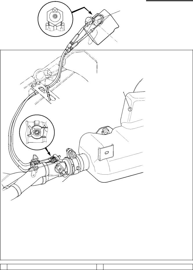
EXCVA (EXHAUST CONTROL VALVE ACTUATOR) AND EXCV (EXHAUST CONTROL VALVE)
EXCVA REMOVAL
•Turn the ignition switch OFF.
•Remove the frame cover. ( 8-8)
• Connect the special tool (Mode select switch) to the dealer mode coupler. ( 4-18)
• After turning the special tool’s switch ON, turn the ignition switch ON.
09930-82720: Mode select switch
LE
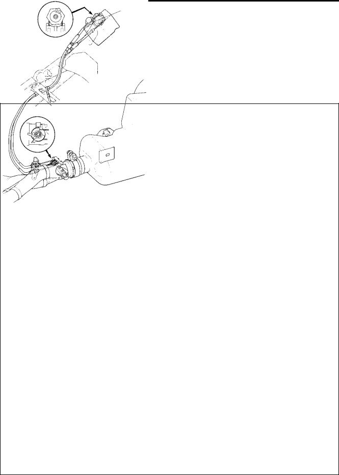
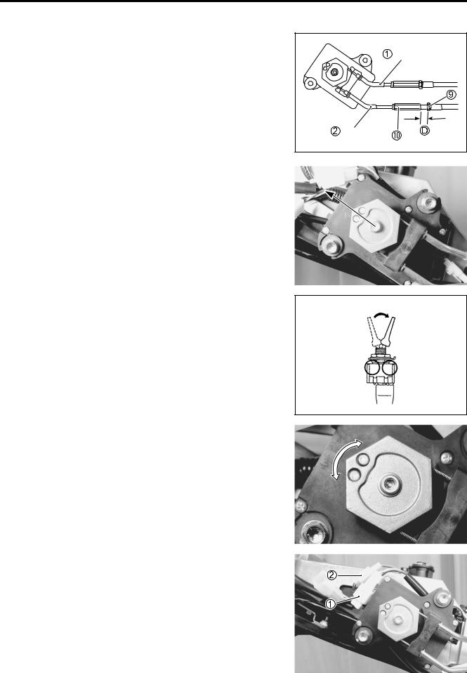
•Measure the thread lengths A and B, before disconnectingP the No.1 and No.2 cables. M 
•Loosen the lock-nut 3 on the No.2 cable 5 and turn in the cable adjuster 4 fully. A
•Loosen the lock-nut 6 onSthe No.1 cable 8 and turn in the cable adjuster 7 fully .
•Disconnect the No.2 cable 5 and then No.1 cable 8 from the EXCVA pulley. 
•Remove the EXCVA mounting bolts 9.
•Remove the EXCVA.
EXHAUST SYSTEM 6-5
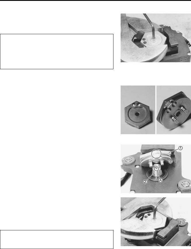
•Hold the EXCVA pulley with an adjustable wrench, and loosen the pulley mounting bolt.
*When loosening or tightening the pulley bolt, be sure to fix the pulley with an adjustable wrench, or EXCVA may get damaged.
*Do not use the adjustable wrench to turn EXCVA pulley so as not to cause damage to the internal gear of EXCVA.
•Remove the EXCVA pulley from the EXCVA body.
EXCVA PULLEY INSPECTION
•Inspect the EXCVA pulley groove for wear and damage.
•If any defects are found, replace the EXCVA pulley with a new one.
|
|
E |
|
|
L |
EXCVA INSTALLATION |
P |
|
|
||
• Install the EXCVA pulley 1 to the shaft 2. |
||
NOTE: |
|
M |
Align the shaft’s line A and cableAslots B as shown. |
||
|
S |
|
•Hold the EXCVA pulley with an adjustable wrench, and then tighten the EXCVA pulley mounting bolt to the specified torque.
EXCVA pulley mounting bolt: 5 N·m (0.5 kgf-m, 3.5 lb-ft)
When loosening or tightening the pulley bolt, be sure to fix the pulley with an adjustable wrench, or EXCVA may get damaged.
EXHAUST SYSTEM 6-7
EXCV CABLE REPLACEMENT
•Lift and support the fuel tank. ( 5-3)
•Check the EXCVA to adjustment position. ( 6-4)
If the EXCVA adjustment is necessary,refer to page 6-8 to -10 for EXCVA ADJUSTMENT setting procedure.
• Disconnect the EXCV cables from the EXCVA pulley. ( 6-4)
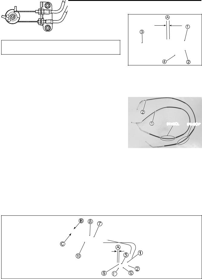
•Measure the thread length A before disconnecting the No.1 cable.
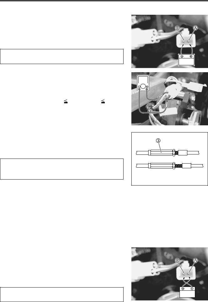
•Disconnect the EXCV cables 1 and 2 from the EXCV pulley 3 and bracket 4.
NOTE: |
|
|
|
The EXCV cables are identified by the letters and shape. |
|
|
|
No.1 cable 1: 01H0CL |
E |
|
|
No.2 cable 2: 01H0OP |
|
|
|
|
|
|
|
|
L |
01H0CL |
01H0OP |
|
|
|
|
|
P |
|
|
•Connect the EXCV cables (1 and 2M) temporarily to the EXCV pulley.
•Turn the adjuster 5 in or outAand adjust the thread length A becomes the measured value before disconnecting ther No.1Scable.
•Tighten the lock-nut 6.
•After adjusting the thread length A, adjust the inner cable length B becomes 41.0 – 42.0 mm (1.61 – 1.65 in) by turning the adjuster 8.
•Tighten the lock-nut 7.
•Turn in the No.2 cable adjuster 0 fully.
•Loosen the lock-nuts A and turn the No.2 cable adjuster B in or out until the inner cable length C becomes 60.0 – 61.0 mm (2.36 – 2.40 in).
•After adjusting the inner cable length C, tighten the lock-nuts A.
EXHAUST SYSTEM 6-9
•To set the EXCV to fully close position, apply 12 V to A and B terminals.
Battery + terminal–– A (Pink lead wire) terminal
Battery - terminal–– B (Gray lead wire) terminal
To prevent the motor damage, stop applying 12 V as
soon as the EXCV reaches fully close position.
12 V
• Turn the ignition switch ON.
• Measure the position sensor output voltage at fully close posi- |
|
|
|
V |
||
tion. |
|
|
|
|
|
|
|
|
|
|
|
|
|
Position sensor output voltage |
|
|
|
|
|
|
|
|
|
|
|
||
EXCV is fully close: 0.5 |
output voltage |
1.3 (V) |
|
|
|
|
(+ Yellow – - B/Br) |
|
|
|
|
|
|
09900-25008: Multi circuit tester set
09900-25009: Needle pointed probe set
Tester knob indication: Voltage ( ) |
L |
||
|
|
||
If the measured voltage is less than specification, adjust the |
E |
||
No.1 cable adjuster as follows: |
P |
|
|
|
|
|
|
• Set the EXCVA to adjustment position. ( 6-4) |
|
|
|
|
M |
|
|
|
|
|
|
Adjusting the No.1 cable with the EXCV fully closed |
|
||
can damage the EXCVA. Be sure to adjust the No.1 |
|
||
cable with the EXCV set inAadjustment position. |
|
|
|
• Turn out the No.1 cableSadjuster 3. |
|
|
|
• Repeat the above procedure until the output voltage becomes specified value.
Position sensor output voltage
EXCV is fully close: 0.5  output voltage
  1.3 (V)
• To next step.
NOTE:
If C46 code is indicated after adjusting the voltage, increase the voltage to 0.9 V.
4th step:
To set the EXCV to fully open position, apply 12 V to A and B terminals.
Battery + terminal–– B (Gray lead wire) terminal Battery - terminal–– A (Pink lead wire) terminal
To prevent the motor damage, stop applying 12 V as
12 V
soon as the EXCV reaches fully open position.

6-10 EXHAUST SYSTEM
Measure the position sensor output voltage at fully open posi-
tion. |
V |
Position sensor output voltage
EXCV is fully open: 3.7  output voltage
  4.5 (V) (+ Yellow – - B/Br)
If the measured voltage is more than specification, adjust the No.2 cable adjuster as follows:
• Set the EXCVA to adjustment position. ( 6-4)
Adjusting the No.2 cable with the EXCV fully opened can damage the EXCVA. Be sure to adjust the No.2 cable with the EXCV set in adjustment position.
• Turn out the No.2 cable adjuster 1. |
|
|
|
|
|
• Repeat the above procedure until the output voltage comes |
LE |
||||
within the specified value. |
|
|
|||
Position sensor output voltage |
|
P |
|||
|
|
|
|
||
EXCV is fully open: 3.7 output voltage |
4.5 (V) |
|
|
||
|
|
M |
|
|
|
• After adjusting the EXCV cables, perform 2nd step to confirm |
|
|
|||
C46 is not indicated. |
A |
|
|
|
|
|
S |
|
|
|
|
EXCV/EXHAUST PIPE, MUFFLER REMOVAL |
|
|
|||
• Remove the frame cover. ( 8-8) |
|
|
|
|
|
• Remove the under cowling. ( 8-5) |
|
|
|
|
|
•Lift and support the fuel tank. ( 5-3)
•Remove the EXCV cables 1, 2 from the EXCV pulley.
•Remove the EXCV cable bracket 3.
•Disconnect the HO2 sensor lead wire coupler. ( 4-107)
•Remove the HO2 sensor. ( 4-107)
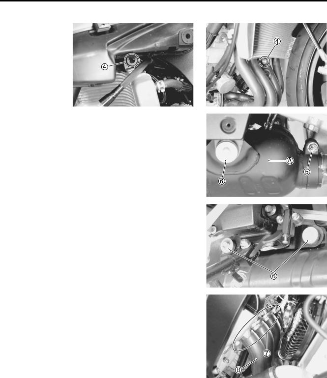
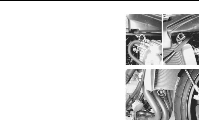
•Remove the radiator mounting bolts 4.
•Move the radiator forward.
Be careful not to bent the radiator fin.
EXHAUST SYSTEM 6-11
•Loosen the exhaust pipe connector bolt 5.
•Remove the muffler mounting bolts 6.
E |
L |
P |
M |
A |
S |
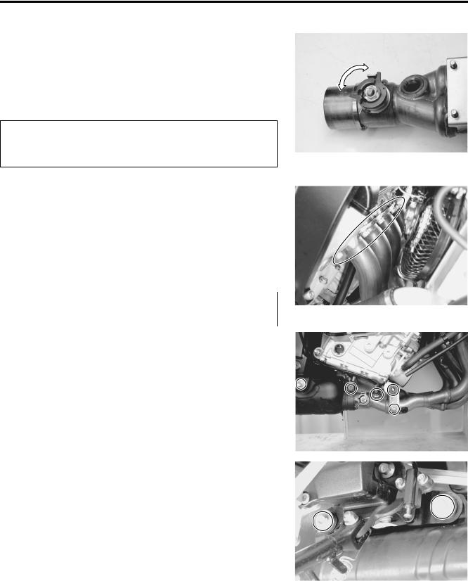
•Loosen the exhaust pipe bolts 7.
•Remove the muffler body A.
•Remove the exhaust pipe bolts 7.
•Remove the exhaust pipe B.
NOTE:
When an exhaust pipe separates, not to throw or drop, have by hand and remove carefully.
6-12 EXHAUST SYSTEM
EXCV INSPECTION
•Turn the EXCV by hand and check that it moves smoothly.
•If it does not move smoothly, replace the EXCV together with the exhaust pipe.
•Decarbonize the EXCV if necessary.
*Do not attempt to disassemble the EXCV.
*The EXCV is available only as the exhaust pipe assembly.
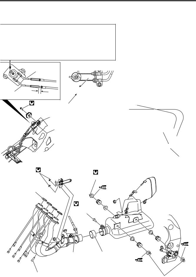
EXCV/EXHAUST PIPE, MUFFLER
INSTALLATION
Install the exhaust pipe and muffler in the reverse order of
removal. Pay attention to the following points. |
|
|
|
• Tighten the exhaust pipe bolts to the specified torque. |
|
||
Exhaust pipe bolt: 23 N·m (2.3 kgf-m, 16.5 lb-ft) |
|
|
|
|
|
|
L |
|
|
|
|
Replace the gaskets and exhaust pipe connector with |
|
||
|
E |
||
the new ones. |
P |
||
|
|
|
|
|
|
|
|
• Tighten the muffler mounting bolts and exhaust pipe connec- |
|
||
tor bolt to the specified torque. |
|
|
|
A |
|
|
|
Exhaust pipe connector bolt: 23 N·m (2.3kgfM-m, 16.5 lb-ft) |
|
||
Muffler mounting bolt: 23 N·m (2.3 kgf-m, 16.5 lb-ft) |
|
||
S |
|
|
|
• Tighten the EXCV cable bracket to the specified torque.
EXCV cable bracket: 10 N·m (1.0 kgf-m, 7.0 lb-ft)
• Tighten the HO2 sensor to the specified torque.
HO2 sensor: 48 N·m (4.8 kgf-m, 35.0 lb-ft)
EXHAUST SYSTEM 6-13
• Tighten the radiator mounting bolts to the specified torque.
Radiator mounting bolt: 10 N·m (1.0 kgf-m, 7.0 lb-ft)
• Install the EXCV cables. ( 6-7)
E
L
P
M
A
S
 48 N
48 N 23 N·m (2.3 kgf-m, 16.5 lb-ft)
 23 N·m (2.3 kgf-m, 16.5 lb-ft)