

Network Plus 2005 In Depth
.pdf112 Chapter 3 TRANSMISSION BASICS AND NETWORKING MEDIA
NET+
1.7
FIGURE 3-39 Multipath signal propagation
The multipath nature of wireless signals is both a blessing and a curse. On one hand, because signals bounce off obstacles, they have a better chance of reaching their destination. In environments such as an office building, wireless services depend on signals bouncing off walls, ceilings, floors, and furniture so that they may eventually reach their destination. Imagine how inconvenient and inefficient it would be, for example, to make sure you were standing within clear view of a transmitter to receive a paging signal.
The downside to multipath signaling is that, because of their various paths, multipath signals travel different distances between their transmitter and a receiver. Thus, multiple instances of the same signal can arrive at a receiver at different times, causing signal delay.
Signal Degradation
No matter what paths wireless signals take, they are bound to run into obstacles. When they do, the original signal issued by the transmitter will experience fading, or a change in signal strength as a result of some of the electromagnetic energy being scattered, reflected, or diffracted after being issued by the transmitter. After fading, the strength of the signal that reaches the receiver is lower than the transmitted signal’s strength. This makes sense because as more waves are reflected, diffracted, or scattered by obstacles, fewer are likely to reach their destination.
As with wire-bound signals, wireless signals also experience attenuation. After a signal is transmitted, the farther it moves away from the transmission antenna the more it weakens.

WIRELESS TRANSMISSION |
Chapter 3 113 |
NET+ |
Just as with wire-bound transmission, wireless signals are amplified (if analog) or repeated (if |
1.7digital) to strengthen the signal so that it can be clearly received. The difference is that the intermediate points through which wireless signals are amplified or repeated are transceivers connected to antennas.
However, attenuation is not the most severe flaw affecting wireless signals. Wireless signals are also susceptible to noise (more often called “interference” in the context of wireless communications). Interference is a significant problem for wireless communications because the atmosphere is saturated with electromagnetic waves. For example, wireless LANs may be affected by cellular phones, mobile phones, or overhead lights.
Interference can distort and weaken a wireless signal in the same way that noise distorts and weakens a wire-bound signal. However, because wireless signals cannot depend on a conduit or shielding to protect them from extraneous EMI, they are more vulnerable to noise. The extent of interference that a wireless signal experiences depends partly on the density of signals within a geographical area. Signals traveling through areas in which many wireless communications systems are in use—for example, the center of a metropolitan area—are the most apt to suffer interference.
Narrowband, Broadband, and Spread Spectrum Signals
Transmission technologies differ according to how much of the wireless spectrum their signals use. An important distinction is whether a wireless service uses narrowband or broadband signaling. In narrowband, a transmitter concentrates the signal energy at a single frequency or in a very small range of frequencies. In contrast to narrowband, broadband uses a relatively wide band of the wireless spectrum. Broadband technologies, as a result of their wider frequency bands, offer higher throughputs than narrowband technologies.
The use of multiple frequencies to transmit a signal is known as spread spectrum technology (because the signal is spread out over the wireless spectrum). In other words, a signal never stays continuously within one frequency range during its transmission. One result of spreading a signal over a wide frequency band is that it requires less power per frequency than narrowband signaling. This distribution of signal strength makes spread spectrum signals less likely to interfere with narrowband signals traveling in the same frequency band.
Spread spectrum signaling, originally used with military wireless transmissions in World War II, remains a popular way of making wireless transmissions more secure. Because signals are split across several frequencies according to a sequence known only to the authorized transmitter and receiver, it is much more difficult for unauthorized receivers to capture and decode spread spectrum signals. To generic receivers, signals issued via spread spectrum technology appear as unintelligible noise.
One specific implementation of spread spectrum is FHSS (frequency hopping spread spectrum). In FHSS transmission, a signal jumps between several different frequencies within a band in a synchronization pattern known only to the channel’s receiver and transmitter. Another type of spread spectrum signaling is called DSSS (direct sequence spread spectrum). In DSSS,

114 |
|
|
Chapter 3 TRANSMISSION BASICS AND NETWORKING MEDIA |
|
|
||||
|
|
|
|
|
|
|
a signal’s bits are distributed over an entire frequency band at once. Each bit is coded so that |
||
NET+ |
|
|
||
1.7the receiver can reassemble the original signal upon receiving the bits.
Fixed versus Mobile
Each type of wireless communication falls into one of two categories: fixed or mobile. In fixed wireless systems, the locations of the transmitter and receiver do not move. The transmitting antenna focuses its energy directly toward the receiving antenna. This results in a point-to- point link. One advantage of fixed wireless is that because the receiver’s location is predictable, energy need not be wasted issuing signals across a large geographical area. Thus, more energy can be used for the signal. Fixed wireless links are used in some data and voice applications. For example, a service provider may obtain data services through a fixed link with a satellite. In cases in which a long distance or difficult terrain must be traversed, fixed wireless links are more economical than cabling.
Not all communications are suited to fixed wireless, however. For example, a waiter who uses a wireless, handheld computer to transmit orders to the restaurant’s kitchen could not use a service that requires him to remain in one spot to send and receive signals. Instead, wireless LANs, along with cellular telephone, paging, and many other services use mobile wireless systems. In mobile wireless, the receiver can be located anywhere within the transmitter’s range. This allows the receiver to roam from one place to another while continuing to pick up its signal.
Now that you understand some characteristics of wireless transmission, you are ready to learn more about the two types of wireless connections used on computer networks: infrared and wireless LANs.
Infrared Transmission
Infrared signals are transmitted by frequencies in the 300-GHz to 300,000-GHz range, which is just above the top of the wireless spectrum as it is defined by the FCC. Infrared frequencies approach the range of visible light in the electromagnetic spectrum, and in fact, some can be seen. Yet these frequencies can also be used to transmit data through space, just as a television remote control sends signals across the room.
On computer networks, infrared transmission is most often used for communications between devices in the same room. For example, printers can connect to computers using infrared transmission, and two PDAs (personal digital assistants), or handheld computers, can synchronize their data through infrared transmission. This type of exchange relies on the devices being close to each other, and in some cases, with a clear, line-of-sight path between them. Although infrared technology has the potential to transmit data at speeds that rival fiber-optic throughput, it also comes with disadvantages. For example, infrared signaling requires more power, travels shorter distances, and maneuvers around obstacles less successfully than the wireless technique used on most modern networks, which is discussed next.
WIRELESS TRANSMISSION |
Chapter 3 115 |
NET+ Wireless LAN (WLAN) Architecture
1.7The most common form of WLAN relies on lower frequencies in the 2.4-2.4835 GHz band, more commonly known as the 2.4-GHz band, to send and receive signals. This set of frequencies is popular for many modern communications services because it is unlicensed in the United States. That is, the FCC does not require users to register their service and reserve sole use of these frequencies.
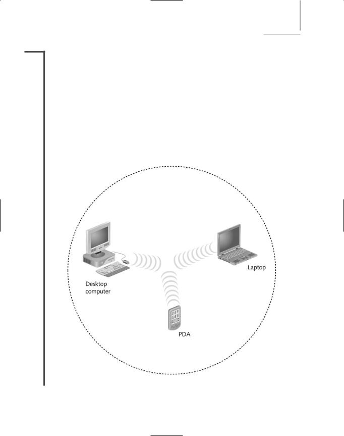
Because they are not bound by cabling paths between nodes and connectivity devices, wireless networks do not follow the same kind of topologies as wire-bound networks. They have their own, different layouts. Smaller wireless networks, in which a small number of nodes closely positioned need to exchange data, can be arranged in an ad hoc fashion. In an ad hoc WLAN, wireless nodes, or stations, transmit directly to each other via wireless NICs without an intervening connectivity device, as shown in Figure 3-40.
FIGURE 3-40 An ad-hoc WLAN
116 |
|
|
Chapter 3 TRANSMISSION BASICS AND NETWORKING MEDIA |
|
|
||||
|
|
|
|
|
|
|
However, an ad-hoc arrangement would not work well for a WLAN with many users or whose |
||
NET+ |
|
|
||
1.6users are spread out over a wide area, or where obstacles could stand in the way of signals between
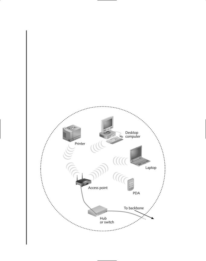
1.7stations. Instead of communicating directly with each other in ad hoc mode, stations on WLANs can use the infrastructure mode, which depends on an intervening connectivity device called an access point. An AP (access point) is a device that accepts wireless signals from multiple nodes and retransmits them to the rest of the network. To cover its intended range, an access point must have sufficient power and be strategically placed so that stations can communicate with it. For instance, if an access point must serve a group of workstations in several offices on one floor in a building, it should probably be located in an open area near the center of that floor. And like other wireless devices, access points contain an antenna connected to their transceivers. An infrastructure WLAN is shown in Figure 3-41 .
It is common for a WLAN to include several access points. The number of access points depends on the number of stations a WLAN connects. The maximum number of stations each access point can serve varies from 10 to 100, depending on the wireless technology used.
FIGURE 3-41 An infrastructure WLAN
WIRELESS TRANSMISSION |
Chapter 3 117 |
NET+ |
Exceeding the recommended maximum leads to a greater incidence of errors and slower over- |
1.6all transmission.
1.7Mobile networking allows wireless nodes to roam from one location to another within a certain range of their AP. This range depends on the wireless access method, the equipment manufacturer, and the office environment. As with other wireless technologies, WLAN signals are subject to interference and obstruction that cause multipath signaling. Therefore, a building with many thick, concrete walls, for example, will limit the effective range of a WLAN more severely than an office that is divided into a few cubicles. In general, stations must remain within 300 feet of an access point to maintain optimal transmission speeds.
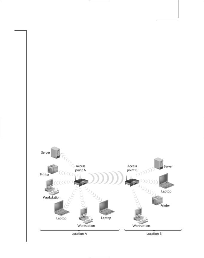
In addition to connecting multiple nodes within a LAN, wireless technology can be used to connect two different parts of a LAN or two separate LANs. Such connections typically use a fixed link with directional antennas between two access points, as shown in Figure 3-42. Because point-to-point links only have to transmit in one direction, they can apply more energy to signal propagation than mobile wireless links. As a result of applying more energy to the signal, their maximum transmission distance is greater. In the case of connecting two WLANs, access points could be as far as 1000 feet apart.
WLANs run over the same protocols and the same operating systems (for example, Unix, Windows, and Novell NetWare) as wire-bound LANs. This compatibility ensures that wireless and wire-bound transmission methods can be integrated on the same network. Only the signaling techniques differ between wireless and wire-bound portions of a LAN. However, techniques for generating and encoding wireless signals vary from one WLAN standard to another. Chapter 6 explains these wireless technologies in detail.
FIGURE 3-42 Wireless LAN interconnection

118 Chapter 3 TRANSMISSION BASICS AND NETWORKING MEDIA
Chapter Summary
Information can be transmitted via two methods: analog or digital. Analog signals are continuous waves that result in variable and inexact transmission. Digital signals are based on electrical or light pulses that represent information encoded in binary form.
In half-duplex transmission, signals may travel in both directions over a medium but in only one direction at a time. When signals may travel in both directions over a medium simultaneously, the transmission is considered full-duplex.
A form of transmission that allows multiple signals to travel simultaneously over one medium is known as multiplexing. In multiplexing, the single medium is logically separated into multiple channels, or subchannels.
Throughput is the amount of data that the medium can transmit during a given period of time. Throughput is usually measured in bits per second and depends on the physical nature of the medium.
Baseband is a form of transmission in which digital signals are sent through direct current pulses applied to the wire. Baseband systems can transmit only one signal, or one channel, at a time. Broadband, on the other hand, uses modulated analog frequencies to transmit multiple signals over the same wire.
Noise is interference that distorts an analog or digital signal. It may be caused by electrical sources, such as power lines, fluorescent lights, copiers, and microwave ovens, or by broadcast signals.
Analog and digital signals both suffer attenuation, or loss of signal, as they travel farther from their sources. To compensate, analog signals are amplified, and digital signals are regenerated through repeaters.
Every network is susceptible to a delay between the transmission of a signal and its receipt. This delay is called latency. The length of the cable contributes to latency, as does the presence of any intervening connectivity device.
Coaxial cable consists of a central copper core surrounded by a plastic insulator, a braided metal shielding, and an outer plastic cover called the sheath. The copper core carries the electromagnetic signal, and the shielding acts as both a protection against noise and a ground for the signal. The insulator layer protects the copper core from the metal shielding. The sheath protects the cable from physical damage.
The type of coaxial cable used to connect cable modems with a broadband cable carrier is RG-6, and it requires an F-Type connector.
Twisted-pair cable consists of color-coded pairs of insulated copper wires, each with a diameter of 0.4 to 0.8 mm, twisted around each other and encased in plastic coating.
STP (shielded twisted-pair) cable consists of twisted wire pairs that are not only individually insulated, but also surrounded by a shielding made of a metallic substance such as foil, to reduce the effects of noise on the signal.

CHAPTER SUMMARY |
Chapter 3 119 |
UTP (unshielded twisted-pair) cabling consists of one or more insulated wire pairs encased in a plastic sheath. As its name suggests, UTP does not contain additional shielding for the twisted pairs. As a result, UTP is both less expensive and less resistant to noise than STP.
10BASE-T is a Physical layer specification for an Ethernet network that is capable of 10Mbps throughput and uses baseband transmission and twisted-pair media. It has a maximum segment length of 100 meters. It follows the 5-4-3 rule, which allows up to five segments between two communicating nodes, permits up to four repeating devices, and allows up to three of the segments to be populated.
100BASE-T (also called Fast Ethernet) is a Physical layer specification for an Ethernet network that is capable of 100-Mbps throughput and uses baseband transmission and twisted-pair media. It has a maximum segment length of 100 meters and allows up to three segments connected by two repeating devices.
1000BASE-T (also called Gigabit Ethernet) is a Physical layer specification for an Ethernet network that is capable of 1000-Mbps (1-Gbps) throughput and uses baseband transmission and twisted-pair media. It has a maximum segment length of 100 meters and allows only one repeating device between segments.
Fiber-optic cable contains one or several glass or plastic fibers in its core. Data is transmitted via pulsing light sent from a laser or light-emitting diode through the central fiber(s). Outside the fiber(s), cladding reflects light back to the core in different patterns that vary depending on the transmission mode.
Fiber-optic cable provides the benefits of very high throughput, very high resistance to noise, and excellent security.
Fiber cable variations fall into two categories: single-mode and multimode. Singlemode fiber uses a small-diameter core, over which light travels mostly down its center, reflecting very few times. This allows single-mode fiber to accommodate high bandwidths and long distances (without requiring repeaters).
Multimode fiber uses a core with a larger diameter, over which many pulses of light travel at different angles. Multimode fiber is less expensive than single-mode fiber.
10BASE-FL is the most popular of the three 10BASE-F standards, each of which specifies a maximum throughput of 10 Mbps over multimode fiber-optic cable. 10BASE-FL can use repeaters to reach a maximum segment length of 2000 meters.
100BASE-FX is a Physical layer specification for a network that can achieve 100Mbps throughput using baseband transmission running on multimode fiber. Its maximum segment length is 2000 meters.
1-Gbps Physical layer standards for fiber-optic networks include 1000BASE-SX and 1000BASE-LX. Because 1000BASE-LX reaches farther and uses a longer wavelength, it is the more popular of the two. 1000BASE-LX can use either singlemode or multimode fiber-optic cable, for which its segments can be up to 550 or 5000 meters, respectively. 1000BASE-SX uses only multimode fiber and can span up to 500 meters.

120Chapter 3 TRANSMISSION BASICS AND NETWORKING MEDIA
1000Base-CX is a Physical layer specification for an Ethernet network that is capable of 1000-Mbps (1-Gbps) throughput and relies on twinaxial cable. It has a maximum segment length of 25 meters and is best suited to short connections within a data center—for example, between two switches or routers.
10-Gbps Physical layer standards include: 10GBASE-SR (“short reach”), which relies on multimode fiber-optic cable and can span a maximum of 300 meters; 10GBASE-ER (“extended reach”), which relies on single-mode fiber and can span a maximum of 10,000 meters; and 10GBaseLR (“long reach”), which also uses single-mode fiber and can span up to 40,000 meters.
In 1991, TIA/EIA released their joint 568 Commercial Building Wiring Standard, also known as structured cabling, for uniform, enterprise-wide, multivendor cabling systems. Structured cabling is based on a hierarchical design that divides cabling into six subsystems: entrance facility, backbone (vertical) wiring, equipment room, telecommunications closet, horizontal wiring, and work area.
The best practice for installing cable is to follow the TIA/EIA 568 specifications and the manufacturer’s recommendations. Be careful not to exceed a cable’s bend radius, untwist wire pairs more than one-half inch, or remove more than one inch of insulation from copper wire. Install plenum-rated cable in ceilings and floors, and run cabling far from where it might suffer physical damage.
Wireless transmission requires an antenna connected to a transceiver. Stations can be fixed or mobile within the antenna’s range.
Wireless transmission is susceptible to interference from EMI. Signals are also affected by obstacles in their paths, which cause them to reflect, diffract, or scatter. A large number of obstacles can prevent wireless signals from ever reaching their destination.
Infrared transmission, which uses frequencies in the 300to 300,000-GHz range, can be used for short-distance transmissions such as sending signals between a computer and a nearby printer. Infrared is impractical for longer distances and many users.
Most modern WLANs (wireless LANs) use frequencies in the 2.4-GHz band. They rely on APs (access points) that transmit and receive signals to and from wireless stations and connectivity devices. APs may connect stations to a LAN or multiple network segments to a backbone.
To determine which transmission media are right for a particular networking environment, you must consider the organization’s required throughput, cabling distance, noise resistance, security, and plans for growth.
Key Terms
1 gigabit per second (Gbps)—1,000,000,000 bits per second.
1 kilobit per second (Kbps)—1000 bits per second.
1 megabit per second (Mbps)—1,000,000 bits per second.

KEY TERMS |
Chapter 3 121 |
1 terabit per second (Tbps)—1,000,000,000,000 bits per second.
10BASE-2—See Thinnet.
10BASE-5—See Thicknet.
10BASE-F—A Physical layer standard for achieving 10-Mbps throughput over multimode fiber-optic cable. Three different kinds of 10BASE-F exist. All require two strands of multimode fiber, in which one strand is used for data transmission and one strand is used for reception, making 10BASE-F a full-duplex technology.
10BASE-FL—The most popular version of the 10BASE-F standard. 10BASE-FL is designed to connect workstations to a LAN or two repeaters and can take advantage of fiber-optic repeating technology to reach its maximum segment length of 2000 meters. 10BASE-FL makes use of the star topology, with its repeaters connected through a bus.
10BASE-T—A Physical layer standard for networks that specifies baseband transmission, twisted-pair media, and 10-Mbps throughput. 10BASE-T networks have a maximum segment length of 100 meters and rely on a star topology.
10GBASE-ER—A Physical layer standard for achieving 10-Gbps data transmission over single-mode, fiber-optic cable. In 10GBASE-ER the “ER” stands for “extended reach.” This standard specifies a star topology and segment lengths up to 40 kilometers.
10GBASE-LR—A Physical layer standard for achieving 10-Gbps data transmission over single-mode, fiber-optic cable using wavelengths of 1310 nanometers. In 10GBASE-LR, the “LR” stands for “long reach.” This standard specifies a star topology and segment lengths up to 10 kilometers.
10GBASE-SR—A Physical layer standard for achieving 10-Gbps data transmission over multimode fiber using wavelengths of 850 nanometers. The maximum segment length for 10GBASE-SR can reach up to 300 meters, depending on the fiber core diameter and modal bandwidth used.
100BASE-FX—A Physical layer standard for networks that specifies baseband transmission, multimode fiber cabling, and 100-Mbps throughput. 100BASE-FX networks have a maximum segment length of 2000 meters. 100BASE-FX may also be called Fast Ethernet.
100BASE-T—A Physical layer standard for networks that specifies baseband transmission, twisted-pair cabling, and 100-Mbps throughput. 100BASE-T networks have a maximum segment length of 100 meters and use the star topology. 100BASE-T is also known as Fast Ethernet.
100BASE-TX—A type of 100BASE-T network that uses two wire pairs in a twisted-pair cable, but uses faster signaling to achieve 100-Mbps throughput. It is capable of full-duplex transmission and requires CAT 5 or higher twisted-pair media.
1000BASE-CX—A Physical layer standard for achieving 1-Gbps throughput over twinaxial copper wire. 1000BASE-CX segments are limited to 25 meters, and are useful mainly to connect devices such as servers or switches.