

Network Plus 2005 In Depth
.pdf222 |
|
|
Chapter 5 NETWORKING HARDWARE |
|
|
||||
|
|
|
|
|
|
|
and even offers routing functions. Switches vary greatly in size and function, so there really is |
||
NET+ |
|
|
||
1.6no such thing as a “typical” switch. Most switches have an internal processor, an operating sys-
2.3tem, memory, and several ports that enable other nodes to connect to it.
NET+ |
Because they have multiple ports, switches can make better use of limited bandwidth and |
1.6prove more cost-efficient than bridges. Each port on the switch acts like a bridge, and each device connected to a switch effectively receives its own dedicated channel. In other words, a switch can turn a shared channel into several channels. From the Ethernet perspective, each dedicated channel represents a collision domain. Because a switch limits the number of devices in a collision domain, it limits the potential for collisions.
Switches have historically been used to replace hubs and ease traffic congestion in LAN workgroups. Some network administrators have replaced backbone routers with switches, because switches provide at least two advantages: better security and better performance. By their nature switches provide better security than many other devices because they isolate one device’s traffic from other devices’ traffic. And because switches provide separate channels for (potentially) every device, performance stands to gain. Applications that transfer a large amount of traffic and are sensitive to time delays, such as videoconferencing applications, benefit from the full use of the channel’s capacity. In addition, hardware and software in a switch are optimized for fast data forwarding.
Switches have their disadvantages, too. Although they contain buffers to hold incoming data and accommodate bursts of traffic, they can become overwhelmed by continuous, heavy traffic. In that event, the switch cannot prevent data loss. Also, although higher-layer protocols, such as TCP, detect the loss and respond with a timeout, others, such as UDP, do not. For packets using such protocols, the number of collisions will mount, and eventually all network traffic grinds to a halt. For this reason, you should plan placement of switches carefully to match backbone capacity and traffic patterns.
Switches have also replaced workgroup hubs on many small and home office networks because their cost has decreased dramatically, they have become easier to install and configure, and they offer the benefit of separating traffic according to port. You might need to install such a switch on a home or office network. The next section describes how to install a simple switch.
Installing a Switch
As with any networking equipment, the best way to ensure that you install a switch properly is to follow the manufacturer’s guidelines. Small workgroup switches are normally simple to install. Many operate properly upon being added to a network. The following steps describe, in general, how to connect multiple nodes to a small switch, and then how to connect that switch to another connectivity device.
1.Make sure the switch is situated where you’re going to keep it after all the cables are connected.
2.Before connecting any cables to the switch’s ports, plug it in and turn it on. Also, when connecting a node to a switch, the node should not be turned on. Otherwise, data irregularities can occur, forcing you to reset the switch.
NET+
1.6
SWITCHES |
Chapter 5 223 |
3.The switch’s power light should illuminate. Most switches perform self-tests when turned on, and blinking lights indicate that these tests are in progress. Wait until the tests are completed (as indicated by a steady, green power light).
4.If you are using a small, inexpensive switch, you might not have to configure it and you can skip to Step 5. But if not, you must use a utility that came with the switch (on CD-ROM, for example) to configure the switch. For example, you may need to assign an IP address to the switch, change the administrator password, or set up management functions. Configuring a switch usually requires connecting it to a PC and then running a configuration utility from a CD-ROM. Refer to the instructions that came with your switch to find out how to configure it.
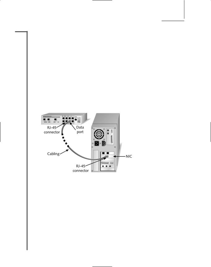
5.Using a straight-through patch cable, connect the node’s NIC to one of the switch’s ports, as shown in Figure 5-20. If you intend to connect this switch to another connectivity device, do not connect patch cables from nodes to the uplink port or to the port adjacent to the uplink port. On most hubs and switches, the uplink port is directly wired to its adjacent port inside the device.
FIGURE 5-20 Connecting a workstation to a switch
6.After all the nodes have been connected to the switch, if you do not plan to connect the switch to another connectivity device, you can turn on the nodes. After the nodes connect to the network through the newly installed switch, check to verify that the switch’s link and traffic lights for each port act as they should, according to the switch’s documentation. Then make sure the nodes can access the network as planned.
7.To connect the switch to a larger network, you can insert one end of a crossover patch cable into the switch’s uplink port, then insert the other end of the cable into a data port on the other connectivity device. Alternately, you can insert one end of a straight-through cable into one of the switch’s data ports, then insert the other end of the straight-through cable into another device’s data port. If you are connecting one switch’s uplink port to another switch’s uplink port, you must use a crossover cable. After connecting the switch to another device, the switch senses the activity on its uplink port, evidenced by its blinking traffic light.

224 |
|
|
Chapter 5 NETWORKING HARDWARE |
|
|
||||
|
|
|
|
|
|
|
Figure 5-21 illustrates a typical way of using a small switch on a small office or home network. |
||
NET+ |
|
|
||
1.6In this example, the switch connects a group of nodes, including workstations, server, and printer, with each other and with an Internet connection.
Switches differ in the method of switching they use—namely, cut-through mode or store and forward mode. These methods of switching are discussed in the next two sections.
FIGURE 5-21 A switch on a small network
Cut-Through Mode
A switch running in cut-through mode reads a frame’s header and decides where to forward the data before it receives the entire packet. Recall that the first 14 bytes of a frame constitute its header, which contains the destination MAC address. This information is sufficient for the switch to determine which port should get the frame and begin transmitting the frame (without bothering to read the rest of the frame and check its accuracy).
What if the frame becomes corrupt? Because the cut-through mode does not allow the switch to read the frame check sequence before it begins transmitting, it can’t verify data integrity in that way. On the other hand, cut-through switches can detect runts, or erroneously shortened packets. Upon detecting a runt, the switch waits to transmit that packet until it determines its integrity. It’s important to remember, however, that runts are only one type of data flaw. Cutthrough switches cannot detect corrupt packets; indeed, they may increase the number of errors found on the network by propagating flawed packets.
The most significant advantage of the cut-through mode is its speed. Because it does not stop to read the entire data packet, a cut-through switch can forward information much more rapidly than a store and forward switch can (as described in the next section). The time-saving advantages to cut-through switching become insignificant, however, if the switch is flooded with traffic. In this case, the cut-through switch must buffer (or temporarily hold) data, just like a store

SWITCHES |
Chapter 5 225 |
NET+ |
and forward switch. Cut-through switches are best suited to small workgroups in which speed |
1.6is important and the relatively low number of devices minimizes the potential for errors.
Store and Forward Mode
In store and forward mode, a switch reads the entire data frame into its memory and checks it for accuracy before transmitting the information. Although this method is more time-con- suming than the cut-through method, it allows store and forward switches to transmit data more accurately. Store and forward mode switches are more appropriate for larger LAN environments, because they do not propagate data errors. In contrast, cut-through mode switches do forward errors, so they may contribute to network congestion if a particular segment is experiencing a number of collisions. In large environments, a failure to check for errors can result in problematic traffic congestion.
Store and forward switches can also transfer data between segments running different transmission speeds. For example, a high-speed network printer that serves 50 students could be attached to a 100-Mbps port on the switch, thereby allowing all of the student workstations to connect to 10-Mbps ports on the same switch. With this scheme, the printer can quickly service multiple jobs. This characteristic makes store and forward mode switches preferable in mixed-speed environments.
NET+ Using Switches to Create VLANs
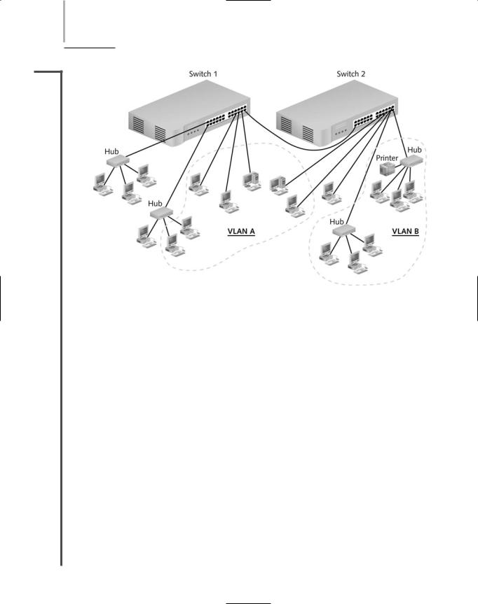
3.8In addition to improving bandwidth usage, switches can create virtual local area networks (VLANs), logically separate networks within networks, by grouping a number of ports into a broadcast domain. A broadcast domain is a combination of ports that make up a Layer 2 segment. Ports in a broadcast domain rely on a Layer 2 device, such as a switch, to forward broadcast frames among them. In contrast to a collision domain, ports in the same broadcast domain do not share a single channel. (Recall that switches separate collision domains.) In the context of TCP/IP networking, a broadcast domain is also known as a subnet. Figure 5-22 illustrates a simple VLAN design.
VLANs can be designed with flexibility. They can include ports from more than one switch or segment. Any type of end node can belong to one or more VLANs. VLANs can link geographically distant users over a WAN, and they can create small workgroups within LANs. Reasons for using VLANs include separating groups of users who need special security or network functions, isolating connections with heavy or unpredictable traffic patterns, identifying groups of devices whose data should be given priority handling, or containing groups of devices that rely on legacy protocols incompatible with the majority of the network’s traffic. One case in which a company might want to implement a VLAN is to allow visitors access to minimal network functions—for example, an Internet connection—without allowing the possibility of access to the company’s data stored on servers. In another example, companies that use their packet-switched networks to carry telephone calls often group all of the voice traffic on a separate VLAN to prevent this unique and potentially heavy traffic from adversely affecting routine client/server tasks.
226 Chapter 5 NETWORKING HARDWARE
NET+
3.8
FIGURE 5-22 A simple VLAN design
On a wireless network, VLANs allow mobile clients to move from one access point’s range to another without losing network functionality or having to reauthenticate with the network. That’s because every wireless client’s MAC address can be associated with an access point, and each access point can be associated with a port on a switch. When these ports are grouped together in a VLAN, it doesn’t matter with which access point a client associates. Because the client stays in the same grouping, it can continue to communicate with the network as if it had remained in one spot.
VLANs are created by properly configuring a switch’s software. This can be done manually through the switch’s configuration utility or automatically using a VLAN software tool. The critical step is to indicate to which VLAN each port belongs. In addition, network managers can specify security parameters, filtering instructions (if the switch should not forward any frames from a certain segment, for example), performance requirements for certain ports, and network addressing and management options.
One potential problem in creating VLANs is that by grouping together certain nodes, you are not merely including those nodes—you are also excluding another group. This means you can potentially cut off a group from the rest of the network. For example, suppose your company’s IT director demands that you assign all executive workstations to their own VLAN, and that you configure the network’s switch to group these users’ computers into a VLAN. After this change, users would be able to exchange data with each other, but they would not be able to download data from the file server or download mail from the mail server, because these servers are not included in their VLAN.
ROUTERS |
Chapter 5 227 |
NET+ |
VLAN configuration can be complex. It requires careful planning to ensure that all users and |
3.8devices that need to exchange data can do so after the VLAN is in operation. It also requires contemplating how the VLAN switch will interact with other devices. For example, in a large office building, you probably would still use hubs or small switches (not configured for a VLAN) as a means of connecting groups of end users to the VLAN switch. If you want users from different VLANs to be able to communicate, you need to connect those VLANs through a Layer 3 device, such as a router or a higher-layer switch, like the ones discussed next.
NET+ Higher-Layer Switches
1.6You have learned that switches operate in Layer 2 of the OSI Model, routers operate in Layer
2.33, and hubs operate in Layer 1. You also learned that the distinctions between bridges, switches, and routers are blurring. Indeed, many networks already use switches that can operate at Layer 3 (Network layer), similar to a router. Manufacturers have also made switches that operate at Layer 4 (Transport layer). A switch capable of interpreting Layer 3 data is called a Layer 3 switch (and sometimes called a routing switch). Similarly, a switch capable of interpreting Layer 4 data is called a Layer 4 switch. These higher-layer switches may also be called routing switches or application switches.
Among other things, the ability to interpret higher-layer data enables switches to perform advanced filtering, statistics keeping, and security functions. But the features of Layer 3 and Layer 4 switches vary widely depending on the manufacturer and the price. (This variability is exacerbated by the fact that key players in the networking trade have not agreed on standards for these switches.) In fact, it’s often hard to distinguish between a Layer 3 switch and a router. In some cases the difference comes down to what the manufacturer has decided to call the device in order to sell more of it. But in general, Layer 3 and Layer 4 switches, like Layer 2 switches, are optimized for fast Layer 2 data handling.
Higher-layer switches can cost three times more than Layer 2 switches, and are typically used as part of a network’s backbone. They would not be appropriate for use on a small, contained LAN or to connect a group of end users to the network.
Routers
NET+ |
A router is a multiport connectivity device that directs data between nodes on a network. |
1.6Routers can integrate LANs and WANs running at different transmission speeds and using a
2.3variety of protocols. Simply put, when a router receives an incoming packet, it reads the packet’s logical addressing information. Based on this, it determines to which network the packet must be delivered. Then it determines the shortest path to that network. Finally it forwards the packet to the next hop in that path. Routers operate at the Network layer (Layer 3) of the OSI Model. They can be devices dedicated to routing, or they can be off-the-shelf computers configured to perform routing services.

228 |
|
|
Chapter 5 NETWORKING HARDWARE |
|
|
||||
|
|
|
|
|
|
|
Recall that the Network layer directs data from one segment or type of network to another. It’s |
||
NET+ |
|
|
||
1.6also the layer that manages logical addressing, using protocols such as IP and IPX. Conse-
2.3quently, unlike bridges and Layer 2 switches, routers are protocol-dependent. They must be designed or configured to recognize a certain Network layer protocol before they can forward data transmitted using that protocol. In general, routers are slower than switches or bridges because they take time to interpret information in Layers 3 and higher.
Traditional standalone LAN routers are being replaced by Layer 3 switches that support the routing functions. However, despite competition from Layer 3 switches, routers are finding niches in specialized applications such as linking large Internet nodes or completing digitized telephone calls. The concept of routing, and everything described in the remainder of this section, applies to both routers and Layer 3 switches.
NET+ Router Features and Functions
1.6A router’s strength lies in its intelligence. Not only can routers keep track of the locations of certain nodes on the network, as switches can, but they can also determine the shortest, fastest path between two nodes. For this reason, and because they can connect dissimilar network types, routers are powerful, indispensable devices on large LANs and WANs. The Internet, for example, relies on a multitude of routers across the world.
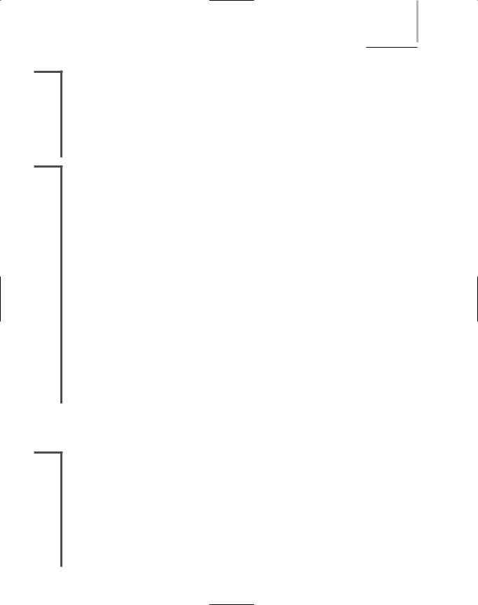
A typical router has an internal processor, an operating system, memory, input and output jacks for different types of network connectors (depending on the network type), and, usually, a management console interface. Three examples of routers are shown in Figure 5-23, with most complex on the left and the simplest on the right. High-powered, multiprotocol routers may have several slot bays to accommodate multiple network interfaces (RJ-45, SC, MTRJ, and so on). A router with multiple slots that can hold different interface cards or other devices is called a modular router. At the other end of the scale are simple, inexpensive routers often used in small offices and homes called SOHO (small office-home office) routers. As with the simple switches described in the previous section, SOHO routers can be added to a network and function properly without significant configuration.
A router is a very flexible device. Although any one can be specialized for a variety of tasks, all routers can do the following:
Connect dissimilar networks.
Interpret Layer 3 addressing and other information (such as quality of service indicators).
Determine the best path for data to follow from point A to point B.
Reroute traffic if a primary path is down but another path is available.
In addition to performing these basic functions, routers may perform any of the following optional functions:
Filter out broadcast transmissions to alleviate network congestion.

ROUTERS |
Chapter 5 229 |
NET+
1.6
FIGURE 5-23 Routers
Prevent certain types of traffic from getting to a network, enabling customized segregation and security.
Support simultaneous local and remote connectivity.
Provide high network fault tolerance through redundant components such as power supplies or network interfaces.
Monitor network traffic and report statistics.
Diagnose internal or other connectivity problems and trigger alarms.
Routers are often categorized according to the scope of the network they serve. A router that directs data between nodes on an autonomous LAN (or one owned and operated by a single organization) is known as an interior router. Such routers do not direct data between an employee’s workstation and a Web server on the Internet. They can, however, direct data between an employee’s workstation and his supervisor’s workstation in an office down the hall. Another type of router is an exterior router. Exterior routers direct data between nodes external to a given autonomous LAN. Routers that operate on the Internet backbone are exterior routers. Between interior and exterior routers are border routers (or gateway routers). Such
230 |
|
|
Chapter 5 NETWORKING HARDWARE |
|
|
||||
|
|
|
|
|
|
|
routers connect an autonomous LAN with a WAN. For example, the router that connects a |
||
NET+ |
|
|
||
1.6business with its ISP is a border router.
Routers may use one of two methods for directing data on the network: static or dynamic routing. Static routing is a technique in which a network administrator programs a router to use specific paths between nodes. Because it does not account for occasional network congestion, failed connections, or device moves, static routing is not optimal. If a router or a segment connected to a router is moved, the network administrator must reprogram the static router’s tables. Static routing requires human intervention, so it is less efficient and accurate than dynamic routing. Dynamic routing, on the other hand, automatically calculates the best path between two nodes and accumulates this information in a routing table. If congestion or failures affect the network, a router using dynamic routing can detect the problems and reroute data through a different path. As a part of dynamic routing, by default, when a router is added to a network, routing protocols update its routing tables. Most networks primarily use dynamic routing, but may include some static routing to indicate, for example, a router of last resort, the router that accepts all unroutable packets.
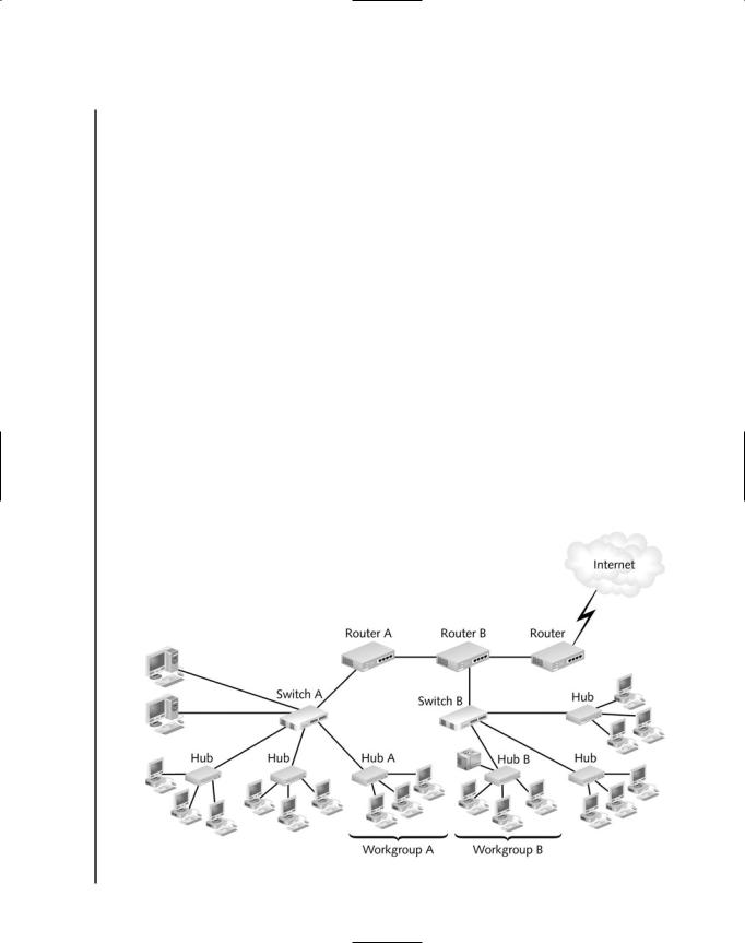
Because of their customizability, routers are not simple to install on sizable networks. Typically, an engineer must be very familiar with routing technology to figure out how to place and configure a router to best advantage. Figure 5-24 gives you some idea of how routers fit into a LAN environment. If you plan to specialize in network design or router configuration, you should research router technology further. You might begin with Cisco System’s online documentation at www.cisco.com/univercd/home/home.htm. Cisco Systems currently provides the majority of networking routers installed in the world.
FIGURE 5-24 The placement of routers on a LAN

ROUTERS |
Chapter 5 231 |
NET+ |
In the setup depicted in Figure 5-24, if a workstation in workgroup A wants to print to the |
1.6printer in workgroup B, it creates a transmission containing the address of the workgroup B printer. Then it sends its packets to hub A. Hub A simply retransmits the message to switch A. When switch A receives the transmission, it checks the MAC address for the printer and determines that the message needs to be forwarded. It forwards the message to router A, which examines the destination network address in each packet and determines the most efficient way of delivering the message. In this example, it sends the data to router B. Before it forwards the data, however, router A increments (increases) the number of hops tallied in all the packets. Each time a packet passes through a router, it makes a hop. Packets can only take a certain number of hops before they are discarded.
After it increments the number of hops tallied in each packet, router A forwards the data to router B. Router B increments each packet’s hop count, reads each packet’s destination network address, and sends them to switch B. Based on the destination MAC address in the packets, switch B decides to forward the message to hub B, which then broadcasts the transmission to workgroup B. The printer picks up the message, and then begins printing.
Routing Protocols: RIP, OSPF, EIGRP, and BGP
Finding the best route for data to take across the network is one of the most valued and sophisticated functions performed by a router. The term best path refers to the most efficient route from one node on a network to another. The best path in a particular situation depends on the number of hops between nodes, the current network activity, the unavailable links, the network transmission speed, and the topology. To determine the best path, routers communicate with each other through routing protocols. Keep in mind that routing protocols are not the same as routable protocols, such as TCP/IP or IPX/SPX, although routing protocols may piggyback on routable protocols. Routing protocols are used only to collect data about current network status and contribute to the selection of the best paths. From these data, routers create routing tables for use with future packet forwarding.
In addition to its ability to find the best path, a routing protocol can be characterized according to its router convergence time, the time it takes for a router to recognize a best path in the event of a change or network outage. Its overhead, or the burden placed on the underlying network to support the routing protocol, is also a distinguishing feature.
Although you do not need to know precisely how routing protocols work to qualify for the Network+ certification, you should be familiar with the most common routing protocols: RIP, OSPF, EIGRP, and BGP. (Several more routing protocols exist, but a discussion of these exceeds the scope of this book.) These four common routing protocols are described in the following list.
RIP (Routing Information Protocol) for IP and IPX—The oldest routing protocol, RIP, which is still widely used, factors in only the number of hops between nodes when determining a path from one point to another. It does not consider network congestion or link speed, for example. RIP is an interior routing protocol, meaning