

Network Plus 2005 In Depth
.pdf272 |
|
|
Chapter 6 TOPOLOGIES AND ACCESS METHODS |
|
|
||||
|
|
|
|
|
|
|
known as a probe, on all available channels within its frequency range. When an access point |
||
NET+ |
|
|
||
1.7finds the probe frame, it issues a probe response. This response contains all the information a station needs to associate with the access point, including a status code and station ID number for that station. After receiving the probe response, a station can agree to associate with that access point. The two nodes begin communicating over the frequency channel specified by the access point.
In passive scanning, a wireless station listens on all channels within its frequency range for a special signal, known as a beacon frame, issued from an access point. The beacon frame contains information that a wireless node requires to associate itself with the access point. For example, the frame indicates the network’s transmission rate and the SSID (Service Set Identifier), a unique character string used to identify an access point. After detecting a beacon frame, the station can choose to associate with that access point. The two nodes agree on a frequency channel and begin communicating. When setting up a WLAN, most network administrators use the access point’s configuration utility to assign a unique SSID (rather than the default SSID provided by the manufacturer). This can contribute to better security and easier network management. For example, the access point used by employees in the Customer Service Department of a company could be assigned the SSID “CustSvc”.
Some WLANs contain multiple access points. If a station detects the presence of several access points, it will choose the one with the strongest signal and the lowest error rate compared to other access points. Notice that a station does not necessarily choose the closest access point. For instance, in the previous example, if another user brought his own access point to the Internet café and his access point had a signal twice as strong as the café’s access point, your laptop would associate with it instead. Other users’ laptops would also associate with his access point (that is, unless those stations were configured to connect to one specific access point, identified by its SSID in the station’s wireless connection properties).
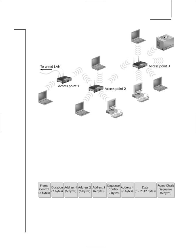
Later, a station might choose a different access point through a process called reassociation. This can happen if a mobile user moves out of one access point’s range and into the range of another, or if the initial access point is experiencing a high rate of errors. On a network with multiple access points, network managers can take advantage of the stations’ scanning feature to automatically balance transmission loads between those access points. Figure 6-17 depicts a WLAN with multiple points.
TIP
The IEEE 802.11 standard specifies communication between two wireless nodes, or stations, and between a station and an access point. However, it does not specify how two access points should communicate. Therefore, when designing an 802.11 network, it is best to use access points manufactured by the same company, to ensure full compatibility.
WIRELESS NETWORKS |
Chapter 6 273 |
NET+
1.7
FIGURE 6-17 A WLAN with multiple access points
Frames
You have learned about some types of overhead required to manage access to the 802.11 wireless networks—for example, ACKs, probes, and beacons. For each function, the 802.11 standard specifies a frame type at the MAC sublayer. These multiple frame types are divided into three groups: control, management, and data. Management frames are those involved in association and reassociation, such as the probe and beacon frames. Control frames are those related to medium access and data delivery, such as the ACK and RTS/CTS frames. Data frames are those that carry the data sent between stations. An 802.11 data frame is illustrated in Figure 6-18.
FIGURE 6-18 Basic 802.11 MAC frame format
Compare the 802.11 data frame with the Ethernet_II data frame pictured in Figure 6-13. Notice that the wireless data frame contains four address fields, rather than two. These four addresses are the source address, transmitter address, receiver address, and destination address. The transmitter and receiver addresses refer to the access point or another intermediary device

274 |
|
|
Chapter 6 TOPOLOGIES AND ACCESS METHODS |
|
|
||||
|
|
|
|
|
|
|
(if used) on the wireless network. The source and destination addresses have the same mean- |
||
NET+ |
|
|
||
1.7ing as they do in the Ethernet_II frame.
Another unique characteristic of the 802.11 data frame is its Sequence Control field. This field is used to indicate how a large packet is fragmented, or subdivided into smaller packets for more reliable delivery. Recall that on wire-bound TCP/IP networks, error checking occurs at the Transport layer of the OSI Model and packet fragmentation, if necessary, occurs at the Network layer. However, in 802.11 networks, error checking and packet fragmentation is handled at the MAC sublayer of the Data Link layer. By handling fragmentation at a lower layer, 802.11 makes its transmission—which is less efficient and more error-prone—transparent to higher layers. This means 802.11 nodes are more easily integrated with 802.3 networks and prevent the 802.11 segments of an integrated network from slowing down the 802.3 segments.
The Frame Control field in an 802.11 data frame holds information about the protocol in use, the type of frame being transmitted, whether the frame is part of a larger, fragmented packet, whether the frame is one that was reissued after an unverified delivery attempt, what type of security the frame uses, and so on. Security is a significant concern with WLANs, because access points are more vulnerable than devices on a wire-bound network. Wireless security is discussed in detail along with other network security later in this book.
Although 802.11b, 802.11a, and 802.11g share all of the MAC sublayer characteristics described in the previous sections, they differ in their coding methods, frequency usage, and ranges. In other words, each varies at the Physical layer. The following sections summarize those differences.
802.11b
In 1999, the IEEE released 802.11b, also known as “Wi-Fi,” for Wireless Fidelity. 802.11b uses DSSS (direct sequence spread spectrum) signaling. Recall that in DSSS, a signal is distributed over the entire bandwidth of the allocated spectrum. 802.11b uses the 2.4–2.4835- GHz frequency range (also called the 2.4-GHz band) and separates it into 14 overlapping 22-MHz channels. 802.11b provides a theoretical maximum of 11-Mbps throughput; actual throughput is typically around 5 Mbps. To ensure this throughput, wireless nodes must stay within 100 meters (or approximately 330 feet) of an access point or each other, in the case of an ad-hoc network. Among all the 802.11 standards, 802.11b was the first to take hold and remains the most popular. It is also the least expensive of all the 802.11 WLAN technologies.
802.11a
Although the 802.11a task group began its standards work before the 802.11b group, 802.11a was released after 802.11b. The 802.11a standard differs from 802.11b and 802.11g in that it uses multiple frequency bands in the 5-GHz frequency range and provides a maximum theoretical throughput of 54 Mbps, though its effective throughput falls generally between 11 and 18 Mbps. 802.11a’s high throughput is attributable to its use of higher frequencies, its unique method of encoding data, and more available bandwidth. Perhaps most significant is that the

WIRELESS NETWORKS |
Chapter 6 275 |
NET+ 5-GHz band is not as congested as the 2.4-GHz band. Thus, 802.11a signals are less likely to
1.7suffer interference from microwave ovens, cordless phones, motors, and other (incompatible) wireless LAN signals. However, higher frequency signals require more power to transmit and travel shorter distances than lower frequency signals. The average geographic range for an 802.11a antenna is 20 meters, or approximately 66 feet. As a result, 802.11a networks require a greater density of access points between the wire-bound LAN and wireless clients to cover the same distance that 802.11b networks cover. The additional access points, as well as the nature of 802.11a equipment, make this standard more expensive than either 802.11b or 802.11g.
802.11g
IEEE’s 802.11g WLAN standard is designed to be just as affordable as 802.11b while increasing its maximum capacity from 11 Mbps to a maximum theoretical throughput of 54 Mbps through different encoding techniques. The effective throughput of 802.11g ranges generally from 20 to 25 Mbps. An 802.11g antenna has a geographic range of 100 meters (or approximately 330 feet).
802.11g, like 802.11b, uses the 2.4-GHz frequency band. In addition to its high throughput, 802.11g benefits from being compatible with 802.11b networks. Thus, if a network administrator installed 802.11b access points on her LAN last year, this year she could add 802.11g access points and laptops, and the laptops could roam between the ranges of the 802.11b and 802.11g access points without an interruption in service. 802.11g’s compatibility with the more established 802.11b has caused many network managers to choose it over 802.11a, despite 802.11a’s comparative advantages.
Bluetooth
In the early 1990s, Ericsson began developing a wireless networking technology for use between multiple devices, including cordless telephones, PDAs, computers, printers, keyboards, telephone headsets, and pagers, in a home. It was designed to carry voice, video, and data signals over the same communications channels. Besides being compatible with a variety of devices, this technology was also meant to be low-cost and short-range. In 1998, Intel, Nokia, Toshiba, and IBM joined Sony Ericsson to form the Bluetooth Special Interest Group (SIG) (its members currently number over 2000 companies), whose aim was to refine and standardize this technology. The resulting standard was named Bluetooth. Bluetooth is a mobile wireless networking standard that uses FHSS (frequency hopping spread spectrum) RF signaling in the 2.4-GHz band. Recall that in FHSS, a signal hops between multiple frequencies within a band in a synchronization pattern known only to the channel’s receiver and transmitter.
Bluetooth was named after King Harald I of Denmark, who ruled in the tenth century. One legend has it that he was so fond of eating blueberries that his teeth were discolored, earning him the nickname “Bluetooth.” This king was also famous for unifying hostile tribes from Denmark, Norway, and Sweden, just as Bluetooth can unify disparate network nodes.
276 |
|
|
Chapter 6 TOPOLOGIES AND ACCESS METHODS |
|
|
||||
|
|
|
|
|
|
|
The original Bluetooth standard, version 1.1, was designed to achieve a maximum theoretical |
||
NET+ |
|
|
||
1.7throughput of 1 Mbps. However, its effective throughput is 723 Kbps, with error correction and control data consuming the remaining bandwidth. The latest version of the standard, version 2.0, was released in 2004. This version uses different encoding schemes that allow Bluetooth to achieve up to 2.1-Mbps throughput. (The newer version of Bluetooth is backward compatible, meaning that devices running version 2.0 can communicate with devices running earlier versions of Bluetooth.) The Bluetooth 1.1 and 1.2 standards recommend that communicating nodes be spaced no farther than 10 meters (or approximately 33 feet) apart. When using Bluetooth version 2.0, communicating nodes can be as far as 30 meters (or approximately 100 feet) apart.
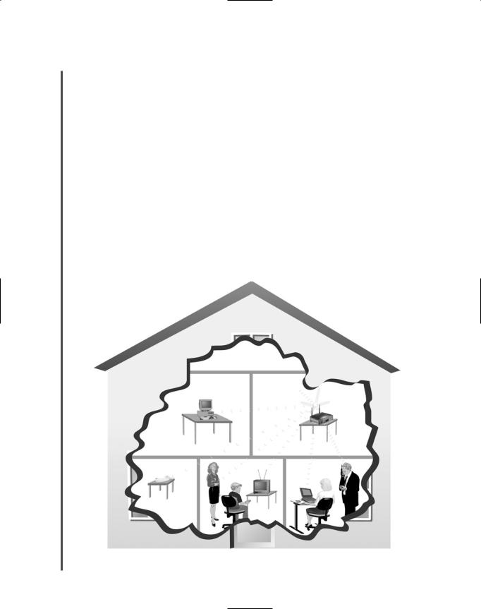
Bluetooth was designed to be used on small networks composed of personal communications devices, also known as PANs (personal area networks). An example of a WPAN (wireless PAN) is shown in Figure 6-19. Bluetooth’s relatively low throughput and short range have made it impractical for business LANs. However, due to commercial support from several influential vendors in the Bluetooth SIG, it has become a popular wireless technology for communicating between cellular telephones and PDAs. Bluetooth has been codified by the IEEE in their 802.15.1 standard, which describes WPAN technology.
FIGURE 6-19 A Wireless personal area network (WPAN)
WIRELESS NETWORKS |
Chapter 6 277 |
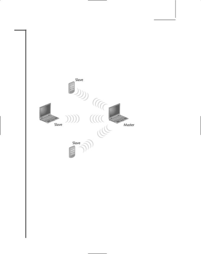
NET+ A Bluetooth PAN is also known as a piconet. The simplest type of piconet is one that contains
1.7one master and one slave, which communicate in a point-to-point fashion with each other. The master determines the frequency hopping sequence and synchronizes the communication. A piconet consisting of only two devices requires no setup. As soon as two devices that are running Bluetooth version 1.x (the most common scenario) come within 10 meters of each other, they can communicate. For example, you might use Bluetooth to send your address data from your PDA to another friend’s PDA. However, a piconet can be larger. With Bluetooth versions 1.x a piconet can contain one master and up to seven slave stations. With Bluetooth 2.0, the number of slaves is unlimited. Figure 6-20 depicts a piconet with one master and three slaves.
FIGURE 6-20 A Bluetooth piconet
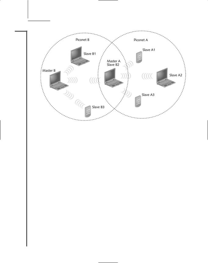
Multiple Bluetooth piconets can be combined to form a scatternet. In a scatternet, each piconet still requires a single master, but a master from one piconet can act as a slave in another piconet, as shown in Figure 6-21. Also, a slave can participate in more than one piconet.
Bluetooth was designed as a better alternative to an older form of wireless communication also used on PANs, infrared signaling.
Infrared (IR)
Even if you don’t run a wireless network in your home, you have probably used infrared (IR) signaling there—for example, to change channels on the TV from your TV remote. You may have noticed that the TV remote works best if you point it directly at the TV and that it does- n’t work at all if you are behind a wall in a different room. That’s because in general, infrared signals depend on a line-of-sight transmission path between the sender and receiver. Just as light can’t pass through a wall, IR signals must follow an unobstructed path between sender
278 Chapter 6 TOPOLOGIES AND ACCESS METHODS
NET+
1.7
FIGURE 6-21 A scatternet with two piconets
and receiver. (However, some IR signals will bounce off of large, angular obstacles and find their way from sender to receiver in a multipath fashion.) Also, IR signals used for communication between computer devices travel only approximately 1 meter (or 3.3 feet). (On the other hand, IR signals from very powerful transmitters could travel hundreds of feet.) Infrared transmission occurs at very high frequencies, in the 300to 300,000-GHz range, and just above the visible spectrum of light. Like Bluetooth, IR technology is relatively inexpensive. IR requires less power than Bluetooth or the 802.11 transmission technologies. The most recent IR standard allows for a maximum throughput of up to 4 Mbps, significantly faster than Bluetooth. But IR’s inability to circumnavigate physical obstacles or travel long distances have limited its uses on modern networks.
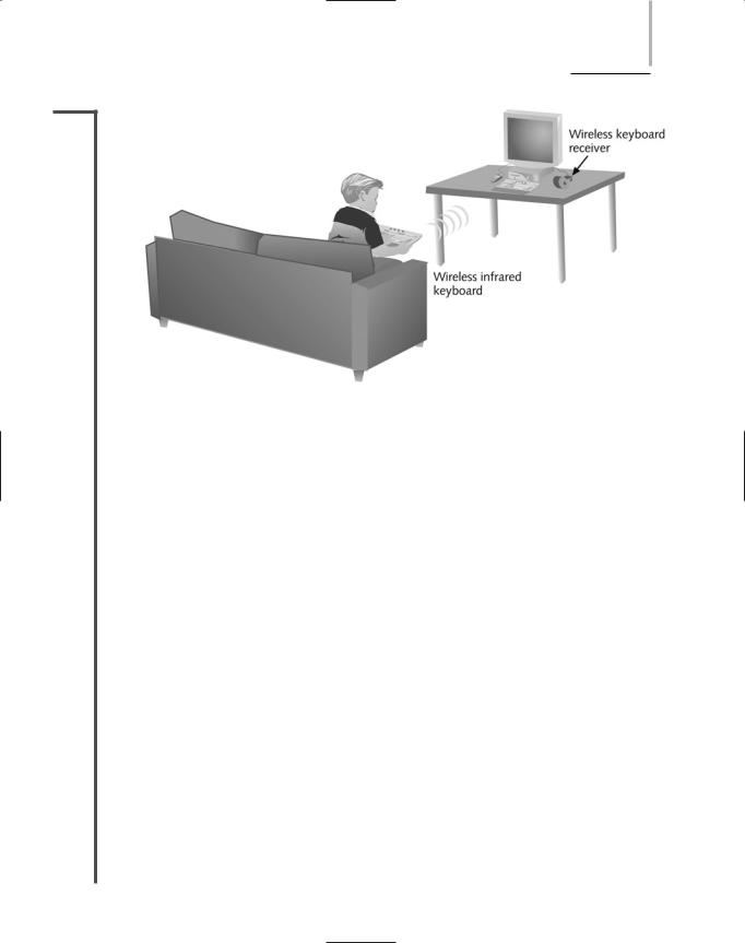
Nevertheless, infrared signaling remains an appropriate option for wireless communication in which devices can be positioned close to each other. IR ports are common on computers and peripherals, and IR signaling is used to exchange data between computers, printers, PDAs, cellular telephones, and other devices. For example, you might purchase a wireless keyboard that can communicate with your computer via infrared signaling. In this case, the IR port on the wireless keyboard must be pointed toward the receiving port. In the case of the keyboard shown in Figure 6-22, the wireless keyboard communicates with a wireless keyboard receiver that is attached to the computer’s keyboard port with a cable. Specifications for using infrared signaling between devices on a network have been established by the IrDA (Infrared Data Association), a nonprofit organization founded in 1994 to develop and promote standards for wireless communication using infrared signals. IrDA is also the term used to refer to the most popular IR networking specifications.
WIRELESS NETWORKS |
Chapter 6 279 |
NET+
1.7
FIGURE 6-22 Infrared transmission
To summarize what you have learned about wireless network standards, Table 6-1 lists the significant characteristics of each standard. Table 6-1 offers a comparison of the common wireless networking standards, their ranges, and throughputs.
Table 6-1 |
Wireless standards |
|
|
|
|
|
Theoretical |
Effective |
Average |
|
Frequency |
Maximum |
Throughput |
Geographic |
Standard |
Range |
Throughput |
(Approximate) |
Range |
|
|
|
|
|
802.11b |
2.4 GHz |
11 Mbps |
5 Mbps |
100 meters (or |
(“Wi-Fi”) |
|
|
|
approximately 330 feet) |
802.11a |
5 GHz |
54 Mbps |
11–18 Mbps |
20 meters (or |
|
|
|
|
approximately 66 feet) |
802.11g |
2.4 GHz |
54 Mbps |
20–25 Mbps |
100 meters (or |
|
|
|
|
approximately 330 feet) |
Bluetooth |
2.4 GHz |
1 Mbps |
723 Kbps |
10 meters (or |
ver. 1.x |
|
|
|
approximately 33 feet) |
Bluetooth |
2.4 GHz |
2.1 Mbps |
1.5 Mbps |
30 meters (or |
ver. 2.0 |
|
|
|
approximately 100 feet) |
IrDA |
300–300,000 GHz |
4 Mbps |
3.5 Mbps |
1 meter (or |
|
|
|
|
approximately 3.3 feet) |
|
|
|
|
|
280 Chapter 6 TOPOLOGIES AND ACCESS METHODS
NET+
1.7
NOTE
The actual geographic range of any wireless technology depends on several factors, including the power of the antenna, physical barriers or obstacles between sending and receiving nodes, and interference in the environment. Therefore, although a technology is rated for a certain average geographic range, it may actually transmit signals in a shorter or longer range.
Chapter Summary
A physical topology is the basic physical layout of a network; it does not specify devices, connectivity methods, or addresses on the network. Physical topologies are categorized into three fundamental geometric shapes: bus, ring, and star.
A bus topology consists of a single cable connecting all nodes on a network without intervening connectivity devices. At either end of a bus network, 50-ohm resistors (terminators) stop signals after they have reached their destination. Without terminators, signals on a bus network experience signal bounce.
In a ring topology, each node is connected to the two nearest nodes so that the entire network forms a circle. Data is transmitted in one direction around the ring. Each workstation accepts and responds to packets addressed to it, then forwards the other packets to the next workstation in the ring.
In a star topology, every node on the network is connected through a central device, such as a hub. Any single cable on a star network connects only two devices, so a cabling problem will affect only two nodes. Nodes transmit data to the hub, which then retransmits the information to the rest of the network segment where the destination node can pick it up.
Few LANs use the simple physical topologies in their pure form. More often, LANs employ a hybrid of more than one simple physical topology. The star-wired ring topology uses the physical layout of a star and the token-passing data transmission method. Data is sent around the star in a circular pattern. Token Ring networks, as specified in IEEE 802.5, use this hybrid topology.
In a star-wired bus topology, groups of workstations are connected to a hub in a star formation; all the hubs are networked via a single bus. This design can cover longer distances than a simple star topology and easily interconnect or isolate different network segments, although it is more expensive than using either the star or bus topology alone. The star-wired bus topology commonly forms the basis for Ethernet and Fast Ethernet networks.
Hubs that service star-wired bus or star-wired ring topologies can be daisy-chained to form a more complex hybrid topology. However, daisy-chaining can only extend a network so far before data errors are apt to occur. In this case, maximum segment and network length limits must be carefully maintained.

CHAPTER SUMMARY |
Chapter 6 281 |
Network backbones may follow serial, distributed, collapsed, or parallel topologies. In a serial topology, two or more internetworking devices are connected to each other by a single cable in a daisy-chain fashion. This is the simplest type of backbone. Hubs or switches are often connected in this way to extend a network.
A distributed backbone consists of a number of connectivity devices connected to a series of central devices in a hierarchy. This topology allows for easy network management and scalability.
The collapsed backbone topology uses a router or switch as the single central connection point for multiple subnetworks. This is risky, because an entire network could fail if the central device fails. Also, if the central connectivity device becomes overtaxed, performance on the entire network suffers.
A parallel backbone is the most fault-tolerant backbone topology. It is a variation of the collapsed backbone arrangement that consists of more than one connection from the central router or switch to each network segment and parallel connections between routers and switches, if more than one is present. Parallel backbones are the most expensive type of backbone to implement.
Network logical topologies describe how signals travel over a network. The two main types of logical topologies are bus and ring. Ethernet networks use a bus logical topology, and Token Ring networks use a ring logical topology.
Switching manages the filtering and forwarding of packets between nodes on a network. Every network relies on one of three types of switching: circuit switching, message switching, or packet switching.
Ethernet employs a network access method called CSMA/CD (Carrier Sense Multiple Access with Collision Detection). All Ethernet networks, independent of their speed or frame type, use CSMA/CD.
On heavily trafficked Ethernet networks, collisions are common. The more nodes that are transmitting data on a network, the more collisions will take place. When an Ethernet network grows to a particular number of nodes, performance may suffer as a result of collisions.
Switching can separate a network segment into smaller logical segments, each independent of the other and supporting its own traffic. The use of switched Ethernet increases the effective bandwidth of a network segment because at any given time fewer workstations vie for the access to a shared channel.
Networks may use one (or a combination) of four kinds of Ethernet data frames. Each frame type differs slightly in the way it codes and decodes packets of data from one device to another. Most modern networks rely on Ethernet_II (“DIX”) frames.
Token Ring networks currently run at either 4, 16, or 100 Mbps, as specified by IEEE 802.5. Token Ring networks use the token-passing routine and a star-ring hybrid physical topology. Workstations connect to the network through MAUs (Multistation Access Units). Token Ring networks may use shielded or unshielded twisted-pair cabling.