

Network Plus 2005 In Depth
.pdf192Chapter 4 NETWORK PROTOCOLS
13._________________________ are any hosts on the Internet that need to look up domain name information.
14._________________________ is a terminal emulation protocol used to log on to remote hosts using the TCP/IP protocol suite.
15.The _________________________ is a simple Application layer protocol used to synchronize the clocks of computers on a network.

Chapter 5
Networking
Hardware
After reading this chapter and completing the exercises, you will be able to:
■Identify the functions of LAN connectivity hardware
■Install and configure a network interface card (NIC, or network adapter)
■Identify problems associated with connectivity hardware
■Describe the factors involved in choosing a NIC, hub, switch, or router
■Discuss the functions of repeaters, hubs, bridges, switches, routers, and gateways, and the OSI Model layers at which they operate
■Describe the uses and types of routing protocols

In Chapter 3, you learned how data is transmitted over cable or through the atmosphere. Now you need to know how data arrives at its destination. To understand this process, it’s helpful to compare data transmission to the means by which the U.S. Postal Service delivers mail: Mail trucks, airplanes, and delivery staff serve as the transmission system that moves information from place to place. Machines and personnel at the post office interpret addresses on the envelopes and either deliver the mail to a transfer point or to your home. Inefficiencies in mail delivery, such as letters being misdirected to the wrong transfer point, frustrate both
the sender and the receiver of the mail and increase the overall cost of delivery.
In data networks, the task of directing information efficiently to the correct destination is handled by hubs, routers, bridges, and switches. In this chapter, you will learn about these devices and their roles in managing data traffic. Material in this chapter relates mostly to functions occurring in the Data Link and Network layers of the OSI Model. Some material also relates to the Physical layer. You will learn the concepts involved in moving data from place to place, including issues related to switching and routing protocols. You will also see pictures of the hardware—hubs, switches, bridges, and routers—that make data transfer possible. (It’s important for you to have an accurate mental image of this equipment because, in a cluttered data closet, it may prove difficult to identify the hardware underneath the wiring.) In addition, you will learn all about network interface cards, which serve as the workstation’s link to the network and are often the source of connectivity problems.
NICs (Network Interface Cards)
NET+ |
Network interface cards (also called NICs, network adapters, or network cards) are connectiv- |
1.6ity devices that enable a workstation, server, printer, or other node to receive and transmit data
2.3over the network media. Nearly all NICs contain a data transceiver, the device that transmits and receives data signals. NICs belong to both the Physical layer and Data Link layer of the OSI Model, because they apply data signals to the wire and assemble or disassemble data frames. They also interpret physical addressing information to ensure data is delivered to its proper destination. In addition, they perform the routines that determine which node has the right to transmit data over a network at any given instant.
NET+ |
Advances in NIC technology are making this hardware smarter than ever. Many can also per- |
1.6form prioritization, network management, buffering, and traffic-filtering functions. On most networks, NICs do not, however, analyze information added by the protocols in Layers 3 through 7 of the OSI Model. For example, they could not determine whether the frames they transmit and receive use IP or IPX datagrams. Nor could they determine whether the Presentation layer has encrypted the data in those frames.

NICS (NETWORK INTERFACE CARDS) |
Chapter 5 195 |
As you learn about installing, configuring, and troubleshooting NICs, you should concentrate first on generalities, then move on to special situations. Because NICs are common to every networking device and every network, knowing as much as possible about them may prove to be the most useful tool you have at your disposal.
NET+ Types of NICs
1.6Before you order or install a NIC in a network device, you need to know what type of interface the device uses. NICs come in a variety of types depending on:
The access method (for example, Ethernet versus Token Ring)
Network transmission speed (for example, 100 Mbps versus 1 Gbps)
Connector interfaces (for example, RJ-45 versus SC)
Type of compatible motherboard or device (for example, PCI)
Manufacturer (popular NIC manufacturers include 3Com, Adaptec, D-Link, IBM, Intel, Kingston, Linksys, Netgear, SMC, and Western Digital, to name just a few)
The following section describes one category of NICs, those that are installed on an expansion board inside a computer.
Internal Bus Standards
If you have worked with PCs or studied for CompTIA’s A+ exam, you are probably familiar with the concept of a bus. A computer’s bus is the circuit, or signaling pathway, used by the motherboard to transmit data to the computer’s components, including its memory, processor, hard disk, and NIC. (A computer’s bus may also be called its system bus or main bus.) Buses differ according to their capacity. The capacity of a bus is defined principally by the width of its data path (expressed in bits) and its clock speed (expressed in MHz). A data path size equals the number of bits that it can transmit in parallel at any given time. In the earliest PCs, buses had an 8-bit data path. Later, manufacturers expanded buses to handle 16 bits of data, then 32 bits. Most new desktop computers use buses capable of exchanging 64 bits of data, and some are even capable of 128 bits. As the number of bits of data that a bus can handle increases, so too does the speed of the devices attached to the bus.
A computer’s bus can be expanded to include devices other than those found on the motherboard. The motherboard contains expansion slots, or openings with multiple electrical contacts, that allow devices such as NICs, modems, or sound cards to connect to the computer’s expanded bus. The devices are found on a circuit board called an expansion card or expansion board. Inserting an expansion board into an expansion slot establishes an electrical connection between the expansion board and the motherboard. Thus, the device connected to the expansion board becomes connected to the computer’s main circuit and part of its bus. With expansion boards connected to its main circuit, a computer can centrally control the device.

196 |
|
|
Chapter 5 NETWORKING HARDWARE |
|
|
||||
|
|
|
|
|
|
|
Multiple bus types exist, and to become part of a computer’s bus, an expansion board must use |
||
NET+ |
|
|
||
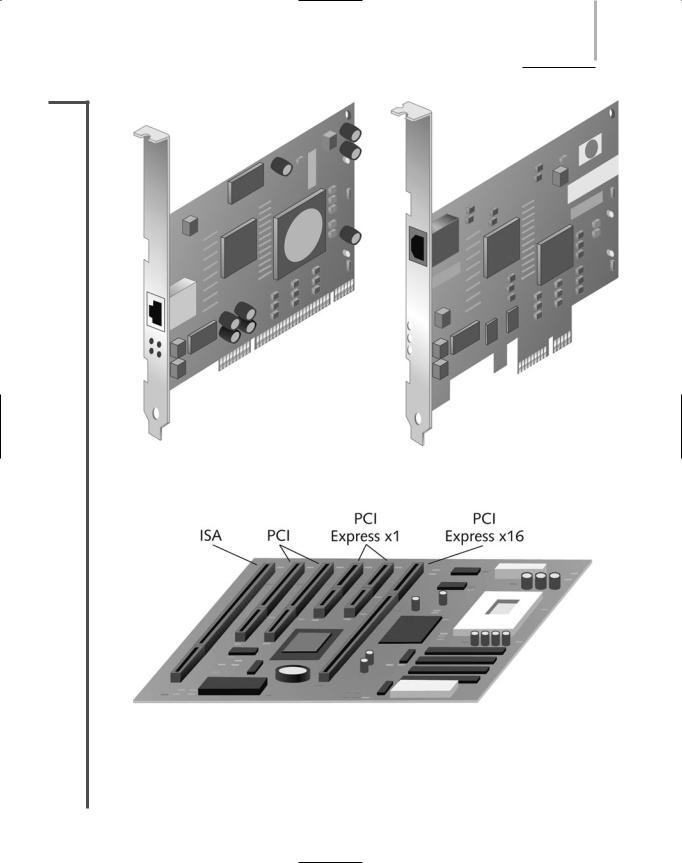
1.6the same bus type. By far the most popular expansion board NIC is one that uses a PCI bus. PCI (Peripheral Component Interconnect) is a 32or 64-bit bus with a 33or 66-MHz clock speed whose maximum data transfer rate is 264 MBps. Intel introduced the first version of PCI in 1992. The latest version, 3.0, was released in 2004 and has become the expansion card type used for nearly all NICs in new PCs. It’s characterized by a shorter connector length and a much faster data transmission capability than previous bus types such as ISA (Industry Standard Architecture), the original PC bus type, developed in the early 1980s to support an 8-bit and later 16-bit data path and a 4.77-MHz clock speed. Another advantage to PCI adapters is that they work within both PCs and Macintosh computers, allowing an organization to standardize on one type of NIC for use with all of its workstations. Figure 5-1 depicts a typical PCI NIC.
A newer version of the PCI standard is PCI Express, which specifies a 64-bit bus with a 133MHz clock speed capable of transferring data at up to 500 MBps per data path, or lane, in full-duplex transmission. PCI Express, which was introduced in 2002, follows a new type of bus design and offers several advantages over the old PCI: more efficient data transfer, support for quality of service distinctions, error reporting and handling, and compatibility with the current PCI software. Also, PCI Express cards are designed to fit into PCs that currently have older PCI slots. (This requires the addition of a small slot behind each of two existing PCI slots. The PCI Express card is then inserted into both PCI slots.) PCI Express slots vary depending on the number of lanes they support: An x1 slot supports a single lane, an x2 slot supports two lanes, and so on. Each lane offers a full-duplex throughput of 500 Mbps. A PCI Express slot can support up to 16 lanes, and an x16 slot can provide 8 Gbps throughput. Computers such as servers that must perform fast data transfer are already using the PCI Express standard, and manufacturers predict that PCI Express will replace PCI in most PCs in coming years. PCI Express is sometimes referred to as PCIe or PCIx. Figure 5-2 depicts a PCI Express x1 NIC.
You can easily determine the type of bus your PC uses by reading the documentation that came with the computer. Someday, however, you may need to replace a NIC on a PC whose documentation is missing. To verify the type of bus a PC uses, you can look inside the PC case. (Later in this chapter, you will learn how to open a computer case, check the computer’s bus, and install a NIC safely.) Most PCs have at least two different types of bus connections on the same motherboard. Figure 5-3 illustrates a motherboard with ISA, PCI, and PCI Express expansion slots.
If a motherboard supports more than one kind of expansion slot, refer to the NIC and PC manufacturers’ guidelines (either in print or on the Web) for information on the preferred type of NIC. If possible, you should choose a NIC that matches the most modern bus on the motherboard. For example, if a PC supports both ISA and PCI, attempt to use a PCI NIC. Although you may be able to use the older bus and NIC types without any adverse effects, some NICs will not work in an older bus if a faster, newer bus is available on the motherboard.
NICS (NETWORK INTERFACE CARDS) |
Chapter 5 197 |
NET+
1.6
FIGURE 5-1 PCI NIC |
FIGURE 5-2 PCI Express x1 NIC |
FIGURE 5-3 A motherboard with multiple expansion slots
198 |
Chapter 5 NETWORKING HARDWARE |
NET+ |
Peripheral Bus Standards |
1.6Some peripheral devices, such as modems or NICs, are attached to the computer’s bus externally rather than internally. PCMCIA (Personal Computer Memory Card International Association), USB (universal serial bus), CompactFlash, or FireWire (IEEE 1394) slots can all be used to connect peripherals such as NICs. One advantage to externally attached NICs is their simple installation. Typically, an externally attached adapter needs only to be plugged into the port to be physically installed. An expansion board NIC, on the other hand, requires the user to turn off the computer, remove its cover, insert the board into an expansion slot, fasten the board in place, replace the cover, and turn on the computer. The oldest externally attached type of NIC still in use today is the PCMCIA adapter.
In 1989, a group of PC system and computer manufacturers formed the Personal Computer Memory Card International Association or PCMCIA. The group’s original goal was to establish a standard method for connecting external memory to a portable computer. Later, seeing the potential for many other uses, PCMCIA revised the standard and offered cards that could connect virtually any type of external device. Now PCMCIA slots may be used to connect external modems, NICs (for either wire-bound or wireless networks), hard disks, or CDROM drives to most laptop computers.
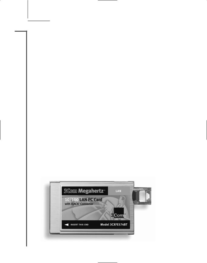
The first standard PCMCIA-standard adapter to be released, called PC Card, specified a 16bit interface running at 8 MHz. However, the PC Card standard was hampered by its slow data transfer rates. In the 1990s, recognizing the need for a faster standard, the PCMCIA group developed CardBus. CardBus specifies a 32-bit interface running at 33 MHz, which matches the PCI expansion board standard. Most modern laptops are equipped with CardBus slots. Figure 5-4 depicts a typical CardBus NIC.
As demand for more and faster data transfer grows, PCMCIA has continued to improve its standards. Recently it released the ExpressCard standard. ExpressCard allows many different external devices to connect to portable computers through a 26-pin interface, and offers data transfer rates of 250 MBps in each direction (for a total of 500 MBps). It uses the same data
FIGURE 5-4 A CardBus NIC

NICS (NETWORK INTERFACE CARDS) |
Chapter 5 199 |
NET+ |
transfer standards as those specified in the PCI Express specification. ExpressCard modules |
1.6come in two sizes: 34 mm (40% smaller than current CardBus modules) and 54 mm wide (the same width as CardBus modules). The smaller sized module will grow more desirable as devices grow thinner and lighter. This new size is also compatible with smaller devices such as PDAs, Tablet PCs, and digital cameras. Over time, PCMCIA expects the ExpressCard standard to replace the CardBus standard. Figure 5-5 shows examples of the two types of ExpressCard modules.
FIGURE 5-5 Express Card modules
NOTE
PCMCIA-standard adapters are often called “credit card adapters” because they are approximately the same size as a credit card.
NET+ |
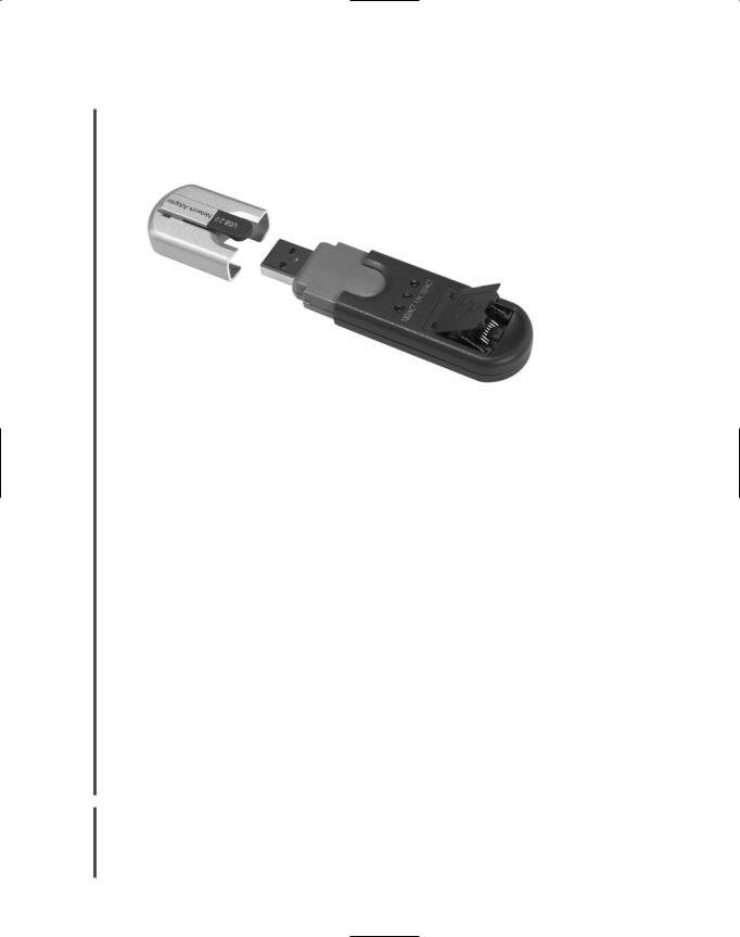
Another type of externally attached NIC is one that relies on a USB (universal serial bus) port. |
1.4USB is a standard interface used to connect multiple types of peripherals, including modems,
1.6mice, audio players, and NICs. The original USB standard was developed in 1995 by a group of computer manufacturers working to make a low-cost, simple-to-install method of connecting peripheral devices to any make or model of computer. Since 1998, USB ports have been supplied on the motherboards of most modern laptop and desktop computers.
USB adapters may follow one of two USB standards: USB 1.1 or USB 2.0. The primary difference between the two standards is speed. The USB 1.1 standard has a maximum data transfer rate of 12 Mbps. The 2.0 standard can reach 480 Mbps, if the correct transfer options are
200 |
|
|
Chapter 5 NETWORKING HARDWARE |
|
|
||||
|
|
|
|
|
|
|
selected and if the attached device is capable of supporting that speed. Most new PCs are |
||
NET+ |
|
|
||
1.4shipped with USB 2.0 ports. Figure 5-6 shows an example of a USB NIC, which has a USB
1.6connector on one end and an RJ-45 receptacle on the other end.
|
FIGURE 5-6 A USB NIC |
|
|
Yet another peripheral bus type is called FireWire. Apple Computer began developing the |
|
|
FireWire standard in the 1980s, and it was codified by the IEEE as the IEEE 1394 standard |
|
|
in 1995. It has been included on the motherboards of Macintosh computers for many years, |
|
|
but has become common on PCs only in the last few years. As with PCMCIA and USB stan- |
|
|
dards, FireWire has undergone several improvements since its inception. Traditional FireWire |
|
|
connections support a maximum throughput of 400 Mbps. A newer version of the standard |
|
|
supports potential throughput rates of over 3 Gbps. |
|
|
FireWire can be used to connect most any type of peripheral, such as a digital camera, VCR, |
|
|
external hard disk, or CD-ROM drive, to a desktop or laptop computer. It can also be used to |
|
|
connect two or more computers on a small network using a bus topology—that is, by linking |
|
|
one computer to another in a daisy-chain fashion. On such a network, FireWire supports a |
|
|
maximum of 63 devices per segment, allows for up to 4.5 meters between nodes, and the chain |
|
|
of FireWire-linked computers can extend no farther than 72 meters from end to end. If your |
|
|
computer doesn’t come with a FireWire port, you can install a FireWire NIC, which is a card |
|
|
(usually PCI or PCMCIA) that contains a FireWire port, to allow for this type of network. |
|
|
FireWire-connected peripherals, such as USBand PCMCIA-connected peripherals, are |
|
|
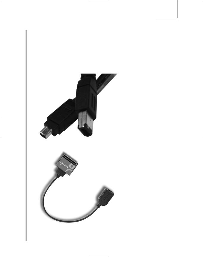
simple to install and supported by most modern operating systems. Connectors come in two |
|
|
varieties: 4-pin and 6-pin. The 6-pin connector contains two pins that can be used to supply |
|
|
power to a peripheral. It is also the one most frequently used for interconnecting computers. |
|
|
FireWire has distinctively small connectors and a thin cable, as shown in Figure 5-7. |
|
|
A fourth external bus standard is the CompactFlash standard. The original group of 12 elec- |
|
NET+ |
||
|
1.6tronics companies that formed the CompactFlash Association (CFA) designed CompactFlash as an ultra-small, removable data and input/output device that would connect to many kinds of peripherals. If you have used a digital camera recently, chances are you’ve saved photos on a
NICS (NETWORK INTERFACE CARDS) |
Chapter 5 201 |
NET+ |
CompactFlash storage card. However, CompactFlash slots can also be used to connect to a net- |
1.6work. The latest CompactFlash standard, 2.0, provides a data transfer rate of 16 MBps. Note that this is significantly slower than any of the current external adapter standards discussed previously. Because of their relatively slower speed, CompactFlash NICs are most likely to be found connecting devices too small to handle PCMCIA slots (for example, PDAs or computers embedded into other devices, such as defibrillators or heart monitors). They are often used in wireless connections, although CompactFlash NICs with RJ-45 connectors do exist, as shown in Figure 5-8.
FIGURE 5-7 FireWire connectors (4-pin and 6-pin)
FIGURE 5-8 A CompactFlash NIC