

Network Plus 2005 In Depth
.pdf212 |
|
|
Chapter 5 NETWORKING HARDWARE |
|
|
||||
|
|
|
|
|
|
|
NICs typically use a memory range in the high memory area, which in hexadecimal notation |
||
NET+ |
|
|
||
1.6equates to the A0000–FFFFF range. As you work with NICs, you will notice that some man-
3.2ufacturers prefer certain ranges. For example, a 3Com PC Card adapter might, by default, choose a range of C8000-C9FFF. An IBM Token Ring adapter might choose a range of D8000-D9FFF.
Memory range settings are less likely to cause resource conflicts than IRQ settings, mainly because there are more available memory ranges than IRQs. Nevertheless, you may run into situations in which you need to change a NIC’s memory address. In such an instance, you may or may not be able to change the memory range from the operating system. Refer to the manufacturer’s guidelines for instructions.
Base I/O Port
The base I/O port setting specifies, in hexadecimal notation, which area of memory will act as a channel for moving data between the NIC and the CPU. Like its IRQ, a device’s base I/O port cannot be used by any other device. Most NICs use two memory ranges for this channel, and the base I/O port settings identify the beginning of each range. Although a NIC’s base I/O port varies depending on the manufacturer, some popular addresses (in hexadecimal notation) are 300 (which means that the range is 300–30F), 310, 280, or 2F8.
You will probably not need to change a NIC’s base I/O port. If you do, bear in mind that, as with IRQ settings, base I/O port settings for PCI cards can be changed in the computer’s CMOS setup utility or sometimes through the operating system.
Firmware Settings
After you have adjusted the NIC’s system resources, you may need to modify its transmission characteristics—for example, whether it uses full duplexing, whether it can detect a network’s speed, or even its MAC address. These settings are held in the adapter’s firmware. As mentioned earlier, firmware constitutes the combination of an EEPROM chip on the NIC and the data it holds. When you change the firmware, you are actually writing to the EEPROM chip on the NIC. You are not writing to the computer’s hard disk. Although most configurable settings can be changed in the operating system or NIC setup software, you may encounter complex networking problems that require a change to firmware settings.
To change a NIC’s firmware, you need a bootable CD-ROM or floppy disk (DOS version 6.0 or higher) containing the configuration or install utility that shipped with the NIC. If you don’t have the utility, you can usually download it from the manufacturer’s Web site. To run the utility, you must start the computer with this CD-ROM or floppy disk inserted. The NIC configuration utility may not run if an operating system or memory management program is already running.
Configuration utilities differ slightly, but all should allow you to view the IRQ, I/O port, base memory, and node address. Some may allow you to change settings such as the NIC’s CPU

NICS (NETWORK INTERFACE CARDS) |
Chapter 5 213 |
NET+ |
utilization, its ability to handle full duplexing, or its capability to be used with only 10BASE- |
1.6T or 100BASE-TX media, for example (although many of these can also be changed through
3.2the NIC’s properties from the operating system interface). The changeable settings vary depending on the manufacturer. Again, read the manufacturer’s documentation to find out the details for your hardware.
NIC configuration utilities also allow you to perform diagnostics—tests of the NIC’s physical components and connectivity. Most of the tests can be performed without additional hardware. However, to perform the entire group of the diagnostic tests on the NIC’s utility disk, you must have a loopback plug. A loopback plug (also called a loopback adapter) is a connector that plugs into a port, such as a serial or parallel or an RJ-45 port, and crosses over the transmit line to the receive line so that outgoing signals can be redirected into the computer for testing. One connectivity test, called a loopback test, requires you to install a loopback plug into the NIC’s media connector. Note that none of the connectivity tests should be performed on a computer connected to a live network. If a NIC fails its connectivity tests, it is probably configured incorrectly. If a NIC fails a physical component test, it may need to be replaced.
NOTE
The word “loopback” implies that signals are routed back toward their source, rather than toward an external destination. When used in the context of NICs, the loopback test refers to a check of the adapter’s ability to transmit and receive signals. Recall that the term “loopback” is also used in the context of TCP/IP protocol testing. In that context, pinging the loopback address provides you with information on TCP/IP functionality.
NET+ Choosing the Right NIC
1.6You should consider several factors when choosing a NIC for your workstation or server. Of course, the most critical factor is compatibility with your existing system. The adapter must match the network’s bus type, access method, connector types, and transmission speed. You also need to ensure that drivers available for that NIC will work with your operating system and hardware.
Beyond these considerations, however, you should examine more subtle differences, such as those that affect network performance. Table 5-2 lists some features available on NICs that specifically influence performance and ease of use. As you review this table, keep in mind that performance is especially important if the NIC will be installed in a server.

214 Chapter 5 NETWORKING HARDWARE
NET+
1.6
Table 5-2 NIC characteristics
NIC Feature |
Function |
Benefit |
Automatic speed |
Enables NICs to sense and adapt to |
Aids configuration and |
selection |
a network’s speed and mode (half- |
performance |
|
or full-duplex) automatically |
|
One or more |
Allows the card to perform some |
Improves performance |
on-board CPUs |
data processing independently of |
|
|
the PC’s CPU |
|
Direct memory |
Enables the card to transfer data to |
Improves performance |
access (DMA) |
the computer’s memory directly |
|
Diagnostic LEDs |
Indicates traffic, connectivity, and, |
Aids in troubleshooting |
(lights on the NIC) |
sometimes, speed |
|
Dual channels |
Effectively creates two NICs in one slot |
Improves performance; |
|
|
suited to servers |
Load balancing |
Allows the NIC’s processor to determine |
Improves performance for |
|
when to switch traffic between internal cards |
heavily-trafficked networks; |
|
|
suited to servers |
“Look Ahead” |
Allows the NIC’s processor to begin |
Improves performance |
transmit and receive |
processing data before it has received the |
|
|
entire packet |
|
Management |
Allows the NIC to perform its own |
capabilities (SNMP) |
monitoring and troubleshooting, usually |
|
through installed application software |
Power management |
Allows a NIC to participate in the |
capabilities |
computer’s power-saving measures; found |
|
on PCMCIA-based adapters |
Aids in troubleshooting; can find a problem before it becomes dire
Increases the life of the battery for laptop computers
RAM buffering |
Provides additional memory on the NIC, |
Improves performance |
|
which in turn provides more space for |
|
|
data buffering |
|
Upgradeable (flash) |
Allows on-board chip memory to be |
Improves ease of use and |
ROM |
upgraded |
performance |
|
|
|
REPEATERS AND HUBS |
Chapter 5 215 |
NET+ |
|
1.6 |
TIP |
The quality of the printed documentation that you receive from a manufacturer about its NICs may vary. What’s more, this documentation may not apply to the kinds of computers or networking environments you are using. To find out more about the type of NIC you are installing or troubleshooting, visit the manufacturer’s Web site.
Repeaters and Hubs
NET+ |
Now that you have learned about the many types of NICs and how to install and configure |
1.6them, you are ready to learn about connectivity devices. As you’ll recall, the telecommunica-
2.3tions closet is the area containing the connectivity equipment (usually for a whole floor of a building). Within the telecommunications closet, horizontal cabling from the workstations attaches to punch-down blocks, patch panels, hubs, switches, routers, and bridges. In addition, telecommunications closets may house repeaters. Repeaters are the simplest type of connectivity devices that regenerate a digital signal.
Repeaters operate in the Physical layer of the OSI Model and, therefore, have no means to interpret the data they retransmit. For example, they cannot improve or correct a bad or erroneous signal; they merely repeat it. In this sense, they are not “intelligent” devices. Since they cannot read higher-layer information in the data frames, repeaters cannot direct data to their destination. Instead, repeaters simply regenerate a signal over an entire segment. It is up to the receiver to recognize and accept its data.
NET+ |
A repeater is limited not only in function, but also in scope. A repeater contains one input port |
1.6and one output port, so it is capable only of receiving and repeating a data stream. Furthermore, repeaters are suited only to bus topology networks. The advantage to using a repeater is that it allows you to extend a network inexpensively. However, because of repeaters’ limitations and the decreasing costs of other connectivity devices, repeaters are rarely used on modern networks. Instead, clients in a workgroup area are more likely to be connected by hubs.
NET+
1.6
2.3
NET+
1.6
At its most primitive, a hub is a repeater with more than one output port. A hub typically contains multiple data ports into which the patch cables for network nodes are connected. Like repeaters, hubs operate at the Physical layer of the OSI Model. A hub accepts signals from a transmitting node and repeats those signals to all other connected nodes in a broadcast fashion. Most hubs also contain one port, called an uplink port, that allows the hub to connect to another hub or other connectivity device. On Ethernet networks, hubs can serve as the central connection point for branches of a star or star-based hybrid topology. On Token Ring networks, hubs are called Multistation Access Units (MAUs).
In addition to connecting Macintosh and PC workstations, hubs can connect print servers, switches, file servers, or other devices to a network. All devices connected to a hub share the same amount of bandwidth and the same collision domain. A collision domain is a logically
216 |
|
|
Chapter 5 NETWORKING HARDWARE |
|
|
||||
|
|
|
|
|
|
|
or physically distinct Ethernet network segment on which all participating devices must detect |
||
NET+ |
|
|
||
1.6and accommodate data collisions. You will learn more about data collisions and Ethernet networks in Chapter 6. Suffice it to say that the more nodes participating in the same collision domain, the higher the likelihood of transmission errors and slower performance.
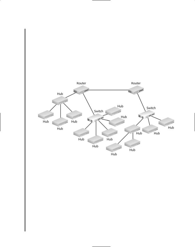
Placement of hubs in a network design can vary. The simplest structure would employ a standalone workgroup hub that is connected to another connectivity device, such as a switch or router. Some networks assign a different hub to each small workgroup, thereby benefiting from not having a single point of failure. No matter what the network design, when using hubs, adhering to a network’s maximum segment and network length limitations is essential. Figure 5-14 suggests how hubs can fit into the overall design of a network.
FIGURE 5-14 Hubs in a network design
Dozens of types of hubs exist. They vary according to the type of media and data transmission speeds they support. Some hubs allow for multiple media connector types or multiple data transmission speeds. The simplest type of hubs—known as passive hubs—do nothing but repeat signals. Like NICs, however, some hubs possess internal processing capabilities. For example, they may permit remote management, filter data, or provide diagnostic information about the network. Hubs that can perform any of these functions are known as intelligent hubs. Intelligent hubs are also called managed hubs, because they can be managed from anywhere on the network.
Standalone hubs, as their name implies, are hubs that serve a group of computers that are isolated from the rest of the network or that form their own small network. They are best suited to small, organizations or home offices. They can be passive or intelligent, and they are simple

NET+
1.6
REPEATERS AND HUBS |
Chapter 5 217 |
to install and connect for a small group of users. Standalone hubs may also be called workgroup hubs. Figure 5-15 depicts a small standalone hub.
FIGURE 5-15 A standalone hub
Standalone hubs do not follow one design, nor do they contain a standard number of ports (though they usually contain 4, 8, 12, or 24 ports). A small, standalone hub that contains only four ports (primarily used for a small or home office) may be called a “hubby,” “hublet,” or a “minihub.” On the other hand, standalone hubs can provide as many as 200 connection ports. The disadvantage to using a single hub for so many connections is that you introduce a single point of failure on the network. A single point of failure is a device or connection on a network that, were it to fail, could cause the entire network or portion of the network to stop functioning. Any sizable network relies on multiple connectivity devices to avoid catastrophic failure.
Stackable hubs resemble standalone hubs, but they are physically designed to be linked with other hubs in a single telecommunications closet. Stackable hubs linked together logically represent one large hub to the network. One benefit to using stackable hubs is that your network or workgroup does not depend on a single hub, which could present a single point of failure. Models vary in the maximum number that can be stacked. For instance, some hub manufacturers restrict the number of their stacked hubs to five; others can be stacked eight units high. Some stackable hubs use a proprietary high-speed cabling system to link the hubs together for better interhub performance.
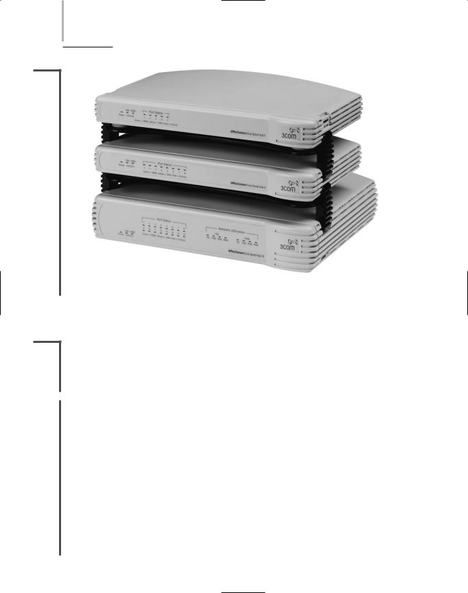
Like standalone hubs, stackable hubs may support a number of different media connectors and transmission speeds and may come with or without special processing features. The number of ports they provide also varies, although you will most often see 6, 12, or 24 ports on a stackable hub. Figure 5-16 shows three stackable hubs. In a telecommunications closet, these hubs would be rack-mounted one above the other, and interconnected.
Hubs have been a mainstay of network connectivity since the first small networks of the 1980s. However, because of their limited features and the fact that they merely repeat signals within a single collision domain, many network administrators have replaced their hubs with switches. To understand how switches operate, it is helpful to learn about bridges first.
218 Chapter 5 NETWORKING HARDWARE
NET+
1.6
FIGURE 5-16 Stackable hubs
Bridges
NET+ |
Bridges are devices that connect two network segments by analyzing incoming frames and |
1.6making decisions about where to direct them based on each frame’s MAC address. They oper-
2.3ate at the Data Link layer of the OSI Model. Bridges look like repeaters, in that they have a single input and a single output port. They differ from repeaters in that they can interpret physical addressing information.
NET+ |
A significant advantage to using bridges over repeaters or hubs is that bridges are protocol- |
1.6independent. For instance, all bridges can connect an Ethernet segment carrying IP-based traffic with an Ethernet segment carrying IPX-based traffic. Some bridges can also connect two segments using different Data Link and Physical layer protocols—for example, an Ethernet segment with a Token Ring segment, or a wire-bound Ethernet segment (802.3) with a wireless Ethernet segment (802.11).
Because they are protocol-ignorant, bridges can move data more rapidly than traditional routers, for example, which do care about Network layer protocol information. On the other hand, bridges take longer to transmit data than either repeaters or hubs, because bridges actually analyze each packet, whereas repeaters and hubs do not.
Another advantage to using bridges is that they can extend an Ethernet network without further extending a collision domain, or segment. In other words, by inserting a bridge into a network, you can add length beyond the maximum limits that apply to segments. Finally, bridges
BRIDGES |
Chapter 5 219 |
NET+ |
can help improve network performance because they can be programmed to filter out certain |
1.6types of frames (for example, unnecessary broadcast frames, whose transmissions squander bandwidth).
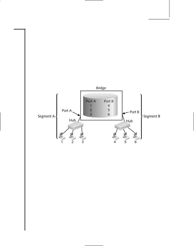
To translate between two segment types, a bridge reads a frame’s destination MAC address and decides to either forward or filter it. If the bridge determines that the destination node is on another segment on the network, it forwards (retransmits) the packet to that segment. If the destination address belongs to the same segment as the source address, the bridge filters (discards) the frame. As nodes transmit data through the bridge, the bridge establishes a filtering database (also known as a forwarding table) of known MAC addresses and their locations on the network. The bridge uses its filtering database to determine whether a packet should be forwarded or filtered, as illustrated in Figure 5-17.
FIGURE 5-17 A bridge’s use of a filtering database
Using Figure 5-17 as an example, imagine that you sit at workstation 1 on segment A of the LAN, and your colleague Abby sits at workstation 2 on segment A. When you attempt to send data to Abby’s computer, your transmission goes through your segment’s hub and then to the bridge. The bridge reads the MAC address of Abby’s computer. It then searches its filtering database to determine whether that MAC address belongs to the same segment you’re on or whether it belongs to a different segment. The bridge can determine only that the MAC address of Abby’s workstation is associated with its port A. If the MAC address belongs to a different segment, the bridge forwards the data to that segment, whose corresponding port identity is also in the filtering database. In this case, however, your workstation and Abby’s workstation reside on the same LAN segment, so the data would be filtered (that is, ignored) and your message would be delivered to Abby’s workstation through segment A’s hub.
Conversely, if you wanted to send data to your supervisor’s computer, which is workstation 5 in Figure 5-17, your transmission would first pass through segment A’s hub and then on to the bridge. The bridge would read the MAC address for your supervisor’s machine (the destination address in your data stream) and search for the port associated with that machine. In this case, the bridge would recognize workstation 5 as being connected to port B, and it would
220 |
|
|
Chapter 5 NETWORKING HARDWARE |
|
|
||||
|
|
|
|
|
|
|
forward the data to that port. Subsequently, the segment B hub would ensure delivery of the |
||
NET+ |
|
|
||
1.6data to your supervisor’s computer.
After you install a new bridge, it uses one of several methods to learn about the network and discover the destination address for each packet it handles. After it discovers this information, it records the destination node’s MAC address and its associated port in its filtering database. Over time, it discovers all nodes on the network and constructs database entries for each.
Standalone bridges became popular in the 1980s and early 1990s; since then, bridging technology has evolved to create more sophisticated bridge devices. But devices other than bridges have also evolved. Equipment manufacturers have improved the speed and functionality of routers and switches while lowering their cost, leaving bridges to become nearly extinct.
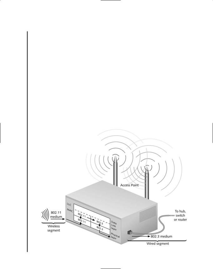
Now, with the advent of wireless LANs, a new kind of bridge has become popular as an inexpensive way to connect the wireless and wire-bound parts of a network, as shown in Figure 5- 18. In fact, you have already learned about these types of bridges, which are also called access points. (An access point without bridging functions could only connect an ad-hoc group of wireless clients with each other. Although such access points exist, they are rare and are generally used to extend wireless segments that at some point connect to a wire-bound portion of the network via a bridge.)
FIGURE 5-18 A bridge connecting wire-bound and wireless LAN segments
SWITCHES |
Chapter 5 221 |
NET+ |
Although bridges are less common than switches on modern wire-bound LANs, understand- |
1.6ing the concept of bridging is essential to understanding how switches work. For example, the bridging process pictured in Figure 5-17 applies to every port on a switch. The next section introduces switches and explains their functions.
Switches
NET+ |
Switches are connectivity devices that subdivide a network into smaller logical pieces, or seg- |
1.6ments. Traditional switches operate at the Data Link layer of the OSI Model, while more mod-
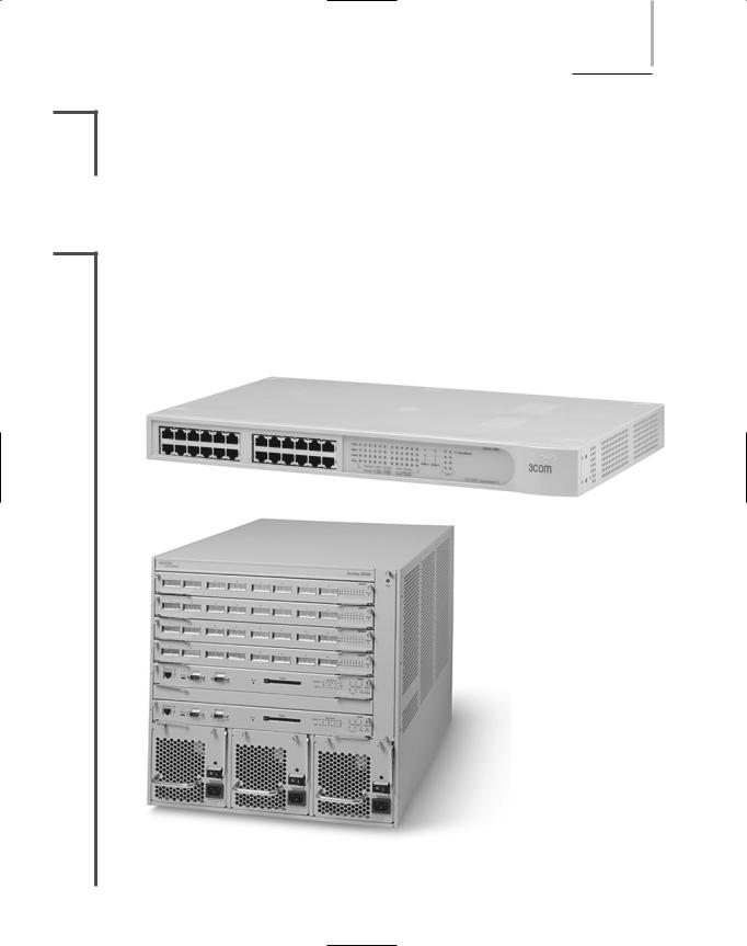
2.3ern switches can operate at Layer 3 or even Layer 4. Like bridges, switches interpret MAC address information. In fact, they can be described as multiport bridges. Figure 5-19 depicts two switches. One is a 24-port switch, useful for connecting nodes in a workgroup, and the other is a high-capacity switch that contains multiple redundant features (such as two NICs)
FIGURE 5-19 Examples of LAN switches