

Network Plus 2005 In Depth
.pdf92 |
Chapter 3 TRANSMISSION BASICS AND NETWORKING MEDIA |
NET+ 100BASE-T (Fast Ethernet)
1.2As networks become larger and handle heavier traffic, Ethernet’s long-standing 10-Mbps lim-
1.3itation becomes a bottleneck that detrimentally affects response time. The need for faster LANs that can use the same infrastructure as the popular 10BASE-T technology has been met by 100BASE-T, also known as Fast Ethernet. 100BASE-T, specified in the IEEE 802.3u standard, enables LANs to run at a 100-Mbps data transfer rate, a tenfold increase from that provided by 10BASE-T, without requiring a significant investment in new infrastructure. 100BASE-T uses baseband transmission and the same star topology as 10BASE-T. It also uses the same RJ-45 modular connectors. Depending on the type of 100BASE-T technology used, it may require CAT 3, CAT 5, or higher UTP.
As with 10BASE-T, nodes on a 100BASE-T network are configured in a star topology. Multiple hubs can be connected to form link segments. However, unlike 10-Mbps Ethernet networks, 100BASE-T networks do not follow the 5-4-3 rule. Because of their faster response requirements, to avoid data errors they require communicating nodes to be even closer. 100BASE-T buses can support a maximum of three network segments connected with two repeating devices. Each segment length is limited to 100 meters. Thus, the overall maximum length between nodes is limited to 300 meters, as shown in Figure 3-23.
FIGURE 3-23 A 100BASE-T network
Two 100BASE-T specifications—100BASE-T4 and 100BASE-TX—have competed for popularity as organizations move to 100-Mbps technology. 100BASE-TX is the version you are most likely to encounter. It achieves its speed by sending the signal 10 times faster and condensing the time between digital pulses as well as the time a station must wait and listen for a signal. 100BASE-TX requires CAT 5 or higher unshielded twisted-pair cabling. Within the cable, it uses the same two pairs of wire for transmitting and receiving data that 10BASE-T uses. Therefore, like 10BASE-T, 100BASE-TX is also capable of full-duplex transmission. Full duplexing can potentially double the effective bandwidth of a 100BASE-T network to 200 Mbps.
FIBER-OPTIC CABLE |
Chapter 3 |
93 |
NET+ 1000BASE-T (Gigabit Ethernet over Twisted-pair)
1.2Because of increasing volumes of data and numbers of users who need to access this data
1.3quickly, even 100 Mbps has not met the throughput demands of some networks. Ethernet technologies designed to transmit data at 1 Gbps are collectively known as Gigabit Ethernet. 1000BASE-T is a standard for achieving throughputs 10 times faster than Fast Ethernet over copper cable, described in IEEE’s 802.3ab standard. In “1000BASE-TX,” “1000” represents 1000 Megabits per second (Mbps), or 1 Gigabit per second (Gbps). “Base” indicates that it uses baseband transmission, and “T” indicates that it relies on twisted-pair wiring. 1000BASE-T achieves its higher throughput by using all four pairs of wires in a CAT 5 or higher cable to both transmit and receive signals, whereas 100BASE-T uses only two of the four pairs. 1000BASE-T also uses a different data encoding scheme than 100BASE-T networks use. However, the standards can be combined on the same network and you can purchase NICs that support 10 Mbps, 100 Mbps, and 1 Gbps via the same connector jack. Because of this compatibility, and the fact that 1000BASE-T can use existing CAT 5 cabling, the 1-Gigabit technology can be added gradually to an existing 100 Mbps network with minimal interruption of service. The maximum segment length on a 1000BASE-T network is 100 meters. It allows for only one repeater. Therefore, the maximum distance between communicating nodes on a 1000BASE-T network is 200 meters.
1000BASE-CX (Gigabit Ethernet over Twinax)
Another standard that supplies 1-Gigabit throughput is 1000BASE-CX. This standard uses either STP or twinaxial cable, which is a cable similar to the coaxial cable discussed earlier in the chapter, but which contains two copper conductors at its center. With this type of cabling, a specialized connector, called an HSSDC, is required. 1000BASE-CX allows only short segment lengths—up to 25 meters. It was designed for connecting servers or connectivity devices over short distances. However, it is rarely used.
Fiber-Optic Cable
NET+ |
Fiber-optic cable, or simply fiber, contains one or several glass or plastic fibers at its center, or |
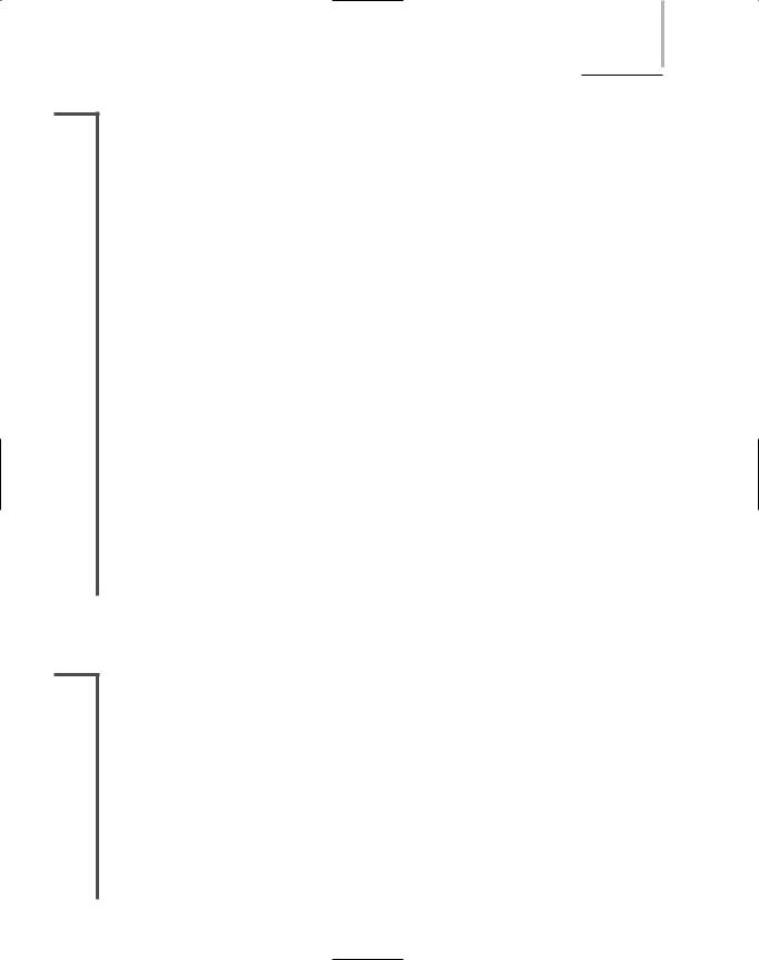
1.5core. Data is transmitted via pulsing light sent from a laser (in the case of 1- and 10-Gigabit technologies) or a light-emitting diode (LED) through the central fibers. Surrounding the fibers is a layer of glass or plastic called cladding. The cladding is a different density from the glass or plastic in the strands. It reflects light back to the core in patterns that vary depending on the transmission mode. This reflection allows the fiber to bend around corners without diminishing the integrity of the light-based signal. Outside the cladding, a plastic buffer protects the cladding and core. Because it is opaque, it also absorbs any light that might escape. To prevent the cable from stretching, and to protect the inner core further, strands of Kevlar (an advanced polymeric fiber) surround the plastic buffer. Finally, a plastic sheath covers the strands of Kevlar. Figure 3-24 shows a fiber-optic cable with multiple, insulated fibers.
94 |
Chapter 3 TRANSMISSION BASICS AND NETWORKING MEDIA |
NET+
1.5
FIGURE 3-24 A fiber-optic cable
Like twisted-pair and coaxial cabling, fiber-optic cabling comes in a number of different varieties, depending on its intended use and the manufacturer. For example, fiber-optic cables used to connect the facilities of large telephone and data carriers may contain as many as 1000 fibers and be heavily sheathed to prevent damage from extreme environmental conditions. At the other end of the spectrum, fiber-optic patch cables for use on LANs may contain only two strands of fiber and be pliable enough to wrap around your hand.
However, all fiber cable variations fall into two categories: single-mode and multimode.
SMF (Single-Mode Fiber)
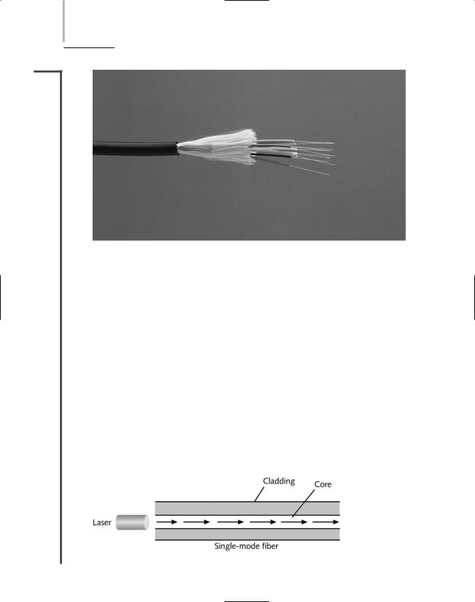
SMF (single-mode fiber) uses a narrow core (less than 10 microns in diameter) through which light generated by a laser travels over one path, reflecting very little. Because it reflects little, the light does not disperse as the signal travels along the fiber. This continuity allows single-mode fiber to accommodate high bandwidths and long distances (without requiring repeaters). Single-mode fiber may be used to connect a carrier’s two facilities. However, it costs too much to be considered for use on typical data networks. Figure 3-25 depicts a simplified version of how signals travel over single-mode fiber.
FIGURE 3-25 Transmission over single-mode fiber-optic cable
FIBER-OPTIC CABLE |
Chapter 3 |
95 |
NET+ MMF (Multimode Fiber)
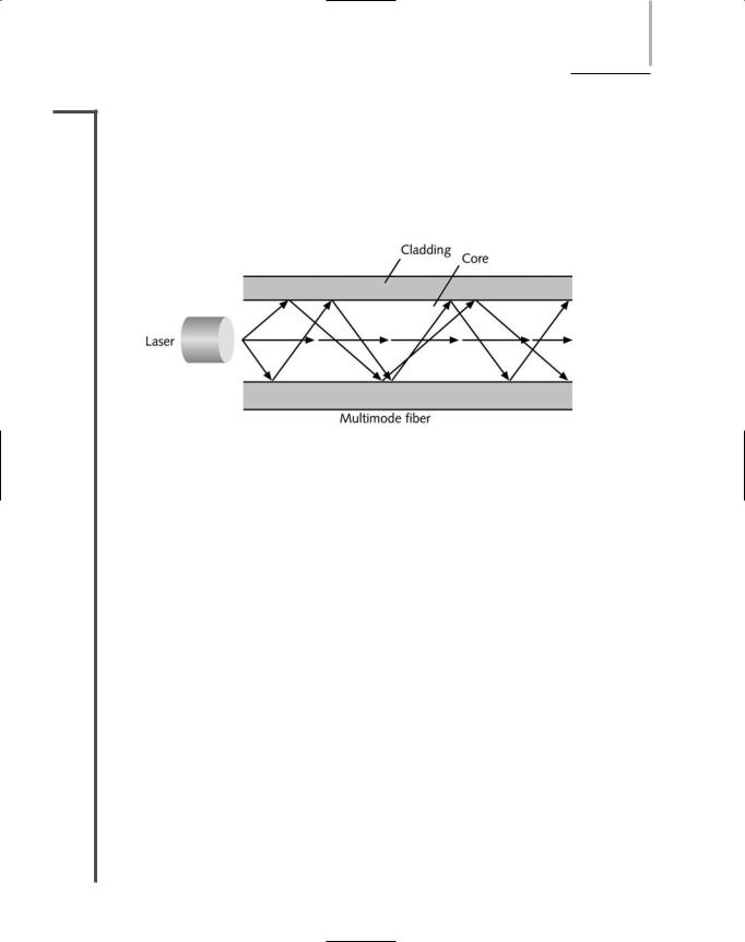
1.5MMF (multimode fiber) contains a core with a larger diameter than single-mode fiber (between 50 and 115 microns in diameter; the most common size is 62.5 microns) over which many pulses of light generated by a laser or LED travel at different angles. It is commonly found on cables that connect a router to a switch or a server on the backbone of a network. Figure 3-26 depicts a simplified view of how signals travel over multimode fiber.
FIGURE 3-26 Transmission over multimode fiber-optic cable
Because of its reliability, fiber is currently used primarily as a cable that connects the many segments of a network. Fiber-optic cable provides the following benefits over copper cabling:
Nearly unlimited throughput
Very high resistance to noise
Excellent security
Ability to carry signals for much longer distances before requiring repeaters than copper cable
Industry standard for high-speed networking
The most significant drawback to the use of fiber is its relatively high cost. Also, fiber-optic cable requires special equipment to splice, which means that quickly repairing a fiber-optic cable in the field (given little time or resources) can be difficult. Fiber’s characteristics are summarized in the following list:
Throughput—Fiber has proved reliable in transmitting data at rates that exceed
10 Gigabits (or 10,000 Megabits) per second. Fiber’s amazing throughput is partly due to the physics of light traveling through glass. Unlike electrical pulses traveling over copper, the light experiences virtually no resistance and, therefore, can be reliably transmitted at faster rates than electrical pulses. In fact, a pure glass strand can accept up to 1 billion laser light pulses per second. Its high throughput capability makes it suitable for network backbones and for serving applications that generate a great deal of traffic, such as video or audio conferencing.
96 |
Chapter 3 TRANSMISSION BASICS AND NETWORKING MEDIA |
NET+
1.5
NET+
1.5
1.4
NET+
1.4
Cost—Fiber-optic cable is the most expensive transmission medium. Because of its cost, most organizations find it impractical to run fiber to every desktop. Not only is the cable itself more expensive than copper cabling, but fiber-optic NICs and hubs can cost as much as five times more than NICs and hubs designed for UTP networks. In addition, hiring skilled fiber cable installers costs more than hiring twisted-pair cable installers.
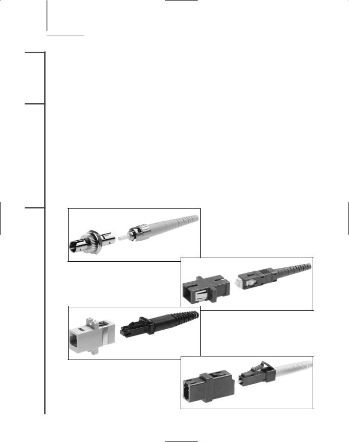
Connector —With fiber cabling, you can use any of 10 different types of connectors. Figure 3-27 shows four connector types: the ST (Straight Tip), SC (Subscriber Connector or Standard Connector), LC (Local Connector), and MT-RJ (Mechanical Transfer Registered Jack) connectors. Each of these connectors can be obtained for single-mode or multimode fiber-optic cable. Existing fiber networks typically use ST or SC connectors. However, MT-RJ connectors are used on the very latest fiber-optic technology. LC and MT-RJ connectors are preferable to ST and SC connectors because of their smaller size, which allows for a higher density of connections at each termination point. The MT-RJ connector is unique because it contains two strands of multimode fiber in a single ferrule, which is a short tube within a connector that encircles the fiber and keeps it properly aligned. With two strands in each ferrule, a single MT-RJ connector provides for duplex signaling.
FIGURE 3-27 Fiber-optic cable connectors
NET+
1.5
FIBER-OPTIC CABLE |
Chapter 3 |
97 |
Noise immunity—Because fiber does not conduct electrical current to transmit signals, it is unaffected by EMI. Its impressive noise resistance is one reason why fiber can span such long distances before it requires repeaters to regenerate its signal.
Size and scalability—Depending on the type of fiber-optic cable used, segment lengths vary from 150 to 40,000 meters. This limit is due primarily to optical loss, or the degradation of the light signal after it travels a certain distance away from its source (just as the light of a flashlight dims after a certain number of feet). Optical loss accrues over long distances and grows with every connection point in the fiber network. Dust or oil in a connection (for example, from people handling the fiber while splicing it) can further exacerbate optical loss.
Just as with twisted-pair and coaxial cabling, IEEE has established Physical layer standards for networks that use fiber-optic cable. Commonly used standards are described in the following sections.
NET+
1.2
1.3
10BASE-FL
In the 10BASE-F standard, the “10” represents its maximum throughput of 10Mbps, “Base” indicates its use of baseband transmission, and “F” indicates that it relies on a medium of fiber-optic cable. In fact, there are at least three different kinds of 10BASE-F. All require two strands of multimode fiber. One strand is used for data transmission and one strand is used for reception, making 10BASE-F a full-duplex technology.
One version of 10BASE-F is 10BASE-FL. 10BASE-FL is an IEEE 802.3 standard distinguished from other 10 Mbps standards that use fiber-optic cable first by its purpose. 10BASEFL is designed to connect workstations to a LAN or to connect two repeaters, whereas the other two 10BASE-F standards are designed for backbone connections. 10BASE-FL is also distinguished by its ability to take advantage of fiber-optic repeating technology. Without repeaters, the maximum segment length for 10BASE-FL is 1000 meters. Using repeaters, it is 2000 meters. 10BASE-FL networks may contain no more than two repeaters. Like 10BASE- T, 10BASE-FL makes use of the star topology, with its repeaters connected through a bus.
Because 10BASE-F technologies involve (expensive) fiber and achieve merely 10-Mbps throughput (whereas the fiber medium is capable of much higher throughput), it is not commonly found on modern networks.
100BASE-FX
The 100BASE-FX standard specifies a network capable of 100-Mbps throughput that uses baseband transmission and fiber-optic cabling. 100BASE-FX requires multimode fiber containing at least two strands of fiber. In half-duplex mode, one strand is used for data transmission, while the other strand is used for reception. In full-duplex implementations, both strands are used for both sending and receiving data. 100BASE-FX has a maximum segment length of 412 meters if half-duplex transmission is used and 2000 meters if full-duplex is used. The standard allows for a maximum of one repeater to connect segments. The 100BASE-FX standard uses a star topology, with its repeaters connected in a bus fashion.

98 |
|
|
Chapter 3 TRANSMISSION BASICS AND NETWORKING MEDIA |
|
|
||||
|
|
|
|
|
|
|
100BASE-FX, like 100BASE-T, is also considered “Fast Ethernet” and is described in IEEE’s |
||
NET+ |
|
|
||
1.2802.3u standard. Organizations switching, or migrating, from UTP to fiber media can com-
1.3bine 100BASE-TX and 100BASE-FX within one network. To do this, transceivers in computers and connectivity devices must have both RJ-45 and SC, ST, LC, or MT-RJ ports. Alternatively, a 100BASE-TX to 100BASE-FX media converter may be used at any point in the network to interconnect the different media and convert the signals of one standard to signals that work with the other standard.
1000BASE-LX
IEEE has specified three different types of 1000Base, or 1 Gigabit, Ethernet technologies for use over fiber-optic cable in its 802.3z standard. Included in this standard is the 1000BASECX standard you learned about previously.
Probably the most common 1-Gigabit Ethernet standard in use today is 1000BASE-LX. The “1000” in 1000BASE-LX stands for 1000-Mbps—or 1 Gbps—throughput. “Base” stands for baseband transmission, and “LX” represents its reliance on “long wavelengths” of 1300 nanometers. (A nanometer equals 0.000000001 meters.) 1000BASE-LX has a longer reach than any other 1-Gigabit technology available today. It relies on either single-mode or multimode fiber. With multimode fiber (62.5 microns in diameter), the maximum segment length is 550 meters. When used with single-mode fiber (8 microns in diameter), 1000BASE-LX can reach 5000 meters. 1000BASE-LX networks can use one repeater between segments. Because of its potential length, 1000BASE-LX is an excellent choice for long backbones—connecting buildings in a MAN, for example, or connecting an ISP with its telecommunications carrier.
1000BASE-SX
1000BASE-SX is similar to 1000BASE-LX in that it has a maximum throughput of 1 Gbps. However, it relies on only multimode fiber-optic cable as its medium. This makes it less expensive to install than 1000BASE-LX. Another difference is that 1000BASE-SX uses short wavelengths of 850 nanometers—thus, the “SX,” which stands for “short.” The maximum segment length for 1000BASE-SX depends on two things: the diameter of the fiber and the modal bandwidth used to transmit signals. Modal bandwidth is a measure of the highest frequency of signal a multimode fiber can support over a specific distance and is measured in MHz-km. It is related to the distortion that occurs when multiple pulses of light, although issued at the same time, arrive at the end of a fiber at slightly different times. The higher the modal bandwidth, the longer a multimode fiber can carry a signal reliably.
When used with fibers whose diameters are 50 microns each, and with the highest possible modal bandwidth, the maximum segment length on a 1000BASE-SX network is 550 meters. When used with fibers whose diameters are 62.5 microns each, and with the highest possible modal bandwidth, the maximum segment length is 275 meters. Only one repeater may be used between segments. Therefore, 1000BASE-SX is best suited for shorter network runs than 1000BASE-LX—for example, connecting a data center with a telecommunications closet in an office building..
FIBER-OPTIC CABLE |
Chapter 3 |
99 |
NET+ 10-Gigabit Fiber-Optic Standards
1.2As you have learned, the throughput potential for fiber-optic cable is extraordinary, and scien-
1.3tists continue to push its limits. Now there are standards for transmitting data at 10-Gbps over fiber, all described in IEEE’s 802.3ae standard. All of the 10-Gigabit options rely on a star topology and allow for only one repeater. They differ according to their signaling methods and maximum allowable segment lengths.
One 10-Gigabit option is 10GBASE-SR, in which the “10G” stands for its maximum throughput of 10 Gigabits per second, “base” stands for baseband transmission, and “SR” stands for “short-reach.” 10GBASE-SR relies on multimode fiber and transmits signals with wavelengths of 850 nanometers. As with the 1-Gigabit standards, the maximum segment length on a 10GBASE-SR network depends on the diameter of the fibers used. It also depends on the modal bandwidth used. For example, if 50-micron fiber is used, with the maximum possible modal bandwidth, the maximum segment length is 300 meters. If 62.5-micron fiber is used with the maximum possible modal bandwidth, a 10GBASE-SR segment can be 66 meters long.
A second standard defined in IEEE 802.3ae is 10GBASE-LR, in which the “10G” stands for 10 Gigabits per second, “base” stands for baseband transmission, and “LR” stands for “longreach.” 10GBASE-LR carries signals with wavelengths of 1310 nanometers through singlemode fiber. Its maximum segment length is 10,000 meters.
A third 10-Gigabit option is 10GBASE-ER, in which “ER” stands for “extended reach.” Like 10GBASE-LR, this standard requires single-mode fiber, through which it transmits signals with wavelengths of 1550 nanometers. It allows for segments up to 40,000 meters, or nearly 25 miles.
Summary of Physical Layer Standards
To obtain Network+ certification, you must be familiar with the different characteristics and limitations of each type of network discussed in this chapter. To put this information in context, Table 3-2 summarizes the characteristics and limitations for Physical layer networking standards, including Ethernet networks that use coaxial cable, twisted-pair cable, and fiberoptic cable.
Table 3-2 Physical layer networking standards
|
Maximum |
Maximum |
|
|
|
Transmission |
Distance per |
Physical |
|
Standard |
Speed (Mbps) |
Segment (m) |
Media |
Topology* |
|
|
|
|
|
10BASE-T |
10 |
100 |
CAT 3 or higher UTP |
Star |
10BASE-FL |
10 |
2000 |
MMF |
Star |
100BASE-TX |
100 |
100 |
CAT 5 or higher UTP |
Star |
1000BASE-T |
1000 |
100 |
CAT 5 or higher UTP |
Star |
|
|
|
(CAT 5e is preferred) |
|

100 Chapter 3 TRANSMISSION BASICS AND NETWORKING MEDIA
NET+
1.2
1.3
Table 3-2 |
Continued |
|
|
|
|
Maximum |
Maximum |
|
|
|
Transmission |
Distance per |
Physical |
|
Standard |
Speed (Mbps) |
Segment (m) |
Media |
Topology* |
|
|
|
|
|
1000BASE-CX 1000 100BASE-FX 100 1000BASE-LX 1000
25 |
Twinaxial cable |
Star |
2000 |
MMF |
Star |
Up to 550, depending |
MMF |
Star |
on wavelength and |
|
|
fiber core diameter |
|
|
1000BASE-LX |
1000 |
5000 |
SMF |
Star |
1000BASE-SX |
1000 |
Up to 500, depending |
MMF |
Star |
|
|
on modal bandwidth |
|
|
|
|
and fiber core diameter |
|
|
10GBASE-SR |
10,000 |
Up to 300, depending |
MMF |
Star |
|
|
on modal bandwidth |
|
|
|
|
and fiber core diameter |
|
|
10GBASE-LR |
10,000 |
10,000 |
SMF |
Star |
10GBASE-ER |
10,000 |
40,000 |
SMF |
Star |
*Although most modern networks use a star-bus hybrid, if you are studying for the Network+ certification exam, you should remember the simple topology on which the network is based.
Cable Design and Management
Organizations that pay attention to their cable plant—the hardware that makes up the enter- prise-wide cabling system—are apt to experience fewer Physical layer network problems, smoother network expansions, and simpler network troubleshooting. Cable management is a significant element of a sound network management strategy.
In 1991, TIA/EIA released its joint 568 Commercial Building Wiring Standard, also known as structured cabling, for uniform, enterprise-wide, multivendor cabling systems. Structured cabling suggests how networking media can best be installed to maximize performance and minimize upkeep. Structured cabling specifies standards without regard for the type of media or transmission technology used on the network. (It does, however assume a network based on the star topology.) In other words, it is designed to work just as well for 10BASE-T networks as it does for 1000BASE-LX networks. Structured cabling is based on a hierarchical design that divides cabling into six subsystems, described in the following list and illustrated in Figure 3-28.

CABLE DESIGN AND MANAGEMENT |
Chapter 3 101 |
FIGURE 3-28 TIA/EIA structured cabling subsystems
Entrance facilities —The point at which a building’s internal cabling plant begins. The entrance facility separates LANs from WANs and designates where the telecommunications service carrier (whether it’s a local phone company, dedicated, or long-distance carrier) accepts responsibility for the (external) wire. The point of division between the service carrier’s network and the internal network is also known as the demarcation point (or demarc).
Backbone wiring—The interconnection between telecommunications closets, equipment rooms, and entrance facilities. On a campus-wide network, the backbone includes not only vertical connectors between floors, or risers, and cabling between equipment rooms, but also cabling between buildings. The TIA/EIA standard designates distance limitations for backbones of varying cable types, as specified in Table 3-3. On modern networks,