

Network Plus 2005 In Depth
.pdf142 |
|
|
Chapter 4 NETWORK PROTOCOLS |
|
|
||||
|
|
|
|
|
|
|
(not shown in Figure 4-3), Computer B will respond with a segment whose sequence number |
||
NET+ |
|
|
||
2.4is 937013560. The two nodes continue communicating this way until Computer A issues a seg-
2.10ment whose FIN flag is set, indicating the end of the transmission.
TCP is not the only core protocol at the Transport layer. A similar but less complex protocol, UDP, is discussed next.
NET+ UDP (User Datagram Protocol)
2.10UDP (User Datagram Protocol), like TCP, belongs to the Transport layer of the OSI Model. Unlike TCP, however, UDP is a connectionless transport service. In other words, UDP offers no assurance that packets will be received in the correct sequence. In fact, this protocol does not guarantee that the packets will be received at all. Furthermore, it provides no error checking or sequencing. Nevertheless, UDP’s lack of sophistication makes it more efficient than TCP. It can be useful in situations where a great volume of data must be transferred quickly, such as live audio or video transmissions over the Internet. In these cases, TCP—with its acknowledgments, checksums, and flow control mechanisms—would only add more overhead to the transmission. UDP is also more efficient for carrying messages that fit within one data packet.
In contrast to a TCP header’s 10 fields, the UDP header contains only four fields: Source port, Destination port, Length, and Checksum. Use of the Checksum field in UDP is optional. Figure 4-4 depicts a UDP segment. Contrast its header with the much larger TCP segment header shown in Figure 4-1.
FIGURE 4-4 A UDP Segment
Now that you understand the functions of and differences between TCP and UDP, you are ready to learn more about the Internet Protocol (IP).
NET+ IP (Internet Protocol)
2.4IP (Internet Protocol) belongs to the Network layer of the OSI Model. It provides informa-
2.10tion about how and where data should be delivered, including the data’s source and destination addresses. IP is the subprotocol that enables TCP/IP to internetwork—that is, to traverse more than one LAN segment and more than one type of network through a router.
TCP/IP |
Chapter 4 143 |
NET+ |
NOTE |
|
2.4 |
||
|
2.10The following sections describe the IP subprotocol as it is used in IPv4 (IP version 4), the original version that has been used for 20 years and is still used by most networks today.
As you know, at the Network layer of the OSI Model, data is formed into packets. In the context of TCP/IP, a packet is also known as an IP datagram. The IP datagram acts as an envelope for data and contains information necessary for routers to transfer data between different LAN segments. IP is an unreliable, connectionless protocol, which means that it does not guarantee delivery of data. Higher-level protocols of the TCP/IP suite, however, use IP to ensure that data packets are delivered to the right addresses. Note that the IP datagram does contain one reliability component, the Header checksum, which verifies only the integrity of the routing information in the IP header. If the checksum accompanying the message does not have the proper value when the packet is received, then the packet is presumed to be corrupt and is discarded; at that point, a new packet is sent.
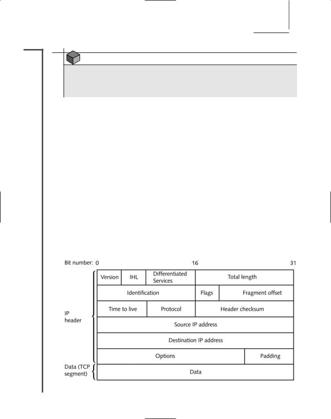
Figure 4-5 depicts the format of an IP datagram. Its fields are described in the following list.
Version—Identifies the version number of the protocol—for example, IPv4 or IPv6. The receiving workstation looks at this field first to determine whether it can read the incoming data. If it cannot, it will reject the packet. Rejection rarely occurs, however, because most TCP/IP-based networks use IPv4. This field is 4 bits long.
Internet Header Length (IHL)—Identifies the number of 4-byte (or 32-bit) blocks in the IP header. The most common header length comprises five groupings, as the
FIGURE 4-5 An IP Datagram
144 Chapter 4 NETWORK PROTOCOLS
NET+
2.4
2.10
minimum length of an IP header is 20 4-byte blocks. This field is important because it indicates to the receiving node where data will begin (immediately after the header ends). The IHL field is 4 bits long.
Differentiated Services (DiffServ) Field—Informs routers what level of precedence they should apply when processing the incoming packet. This field is 8 bits long. It used to be called the Type of Service (ToS) field, and its purpose was the same as the re-defined Differentiated Services field. However, the ToS specification allowed only eight different values regarding the precedence of a datagram, and the field was rarely used. Differentiated Services allows for up to 64 values and a greater range of priority handling options.
Total length—Identifies the total length of the IP datagram, including the header and data, in bytes. An IP datagram, including its header and data, cannot exceed 65,535 bytes. The Total length field is 16 bits long.
Identification—Identifies the message to which a datagram belongs and enables the receiving node to reassemble fragmented messages. This field and the following two fields, Flags and Fragment offset, assist in reassembly of fragmented packets. The Identification field is 16 bits long.
Flags—Indicates whether a message is fragmented and, if it is fragmented, whether this datagram is the last in the fragment.
Fragment offset—Identifies where the datagram fragment belongs in the incoming set of fragments. This field is 13 bits long.
Time to live (TTL)—Indicates the maximum time that a datagram can remain on the network before it is discarded. Although this field was originally meant to represent units of time, on modern networks it represents the number of times a datagram has been forwarded by a router, or the number of router hops it has endured. The TTL for datagrams is variable and configurable, but is usually set at 32 or 64. Each time a datagram passes through a router, its TTL is reduced by 1. When a router receives a datagram with a TTL equal to 1, it discards that datagram (or more precisely, the frame to which it belongs). The TTL field in an IP datagram is 8 bits long.
Protocol—Identifies the type of Transport layer protocol that will receive the datagram (for example, TCP or UDP). This field is 8 bits long.
Header checksum—Allows the receiving node to calculate whether the IP header has been corrupted during transmission. This field is 16 bits long.
Source IP address—Identifies the full IP address (or Network layer address) of the source node. This field is 32 bits long.
Destination IP address—Indicates the full IP address (or Network layer address) of the destination node. This field is 32 bits long.
Options—May contain optional routing and timing information. The Options field varies in length.
|
TCP/IP |
Chapter 4 |
|
145 |
|
|
|||
|
|
|
|
|
|
Padding—Contains filler bits to ensure that the header is a multiple of 32 bits. The |
|||
NET+ |
||||
2.4 |
length of this field varies. |
|
|
|
2.10Data—Includes the data originally sent by the source node, plus information added by TCP in the Transport layer. The size of the Data field varies.
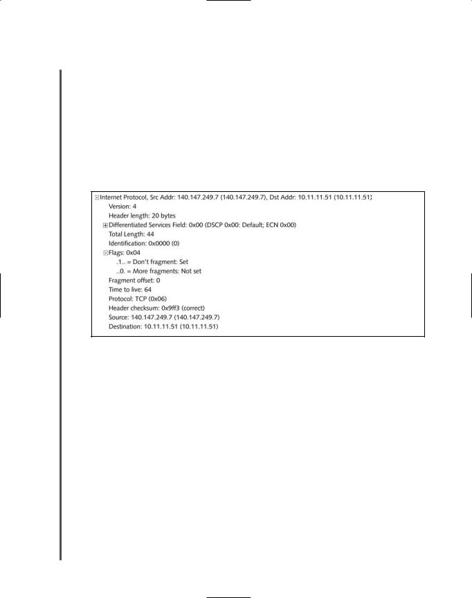
In the Chapter 2 discussion of the Network layer functions, you were introduced to IP and the data contained in its packets. You also saw an example of IP packet data from an actual HTTP request. However, you might not have understood what all of the data meant. Now that you are familiar with the fields of an IP datagram, you can interpret its contents. Figure 4-6 offers another look at the IP packet, with an interpretation below.
FIGURE 4-6 IP Datagram data
Begin interpreting the datagram with the Version field, which indicates that this transmission relies on version 4 of the Internet Protocol, which is common for modern networks. Next, notice that the datagram has a header length of 20 bytes. Because this is the minimum size for an IP header, you can deduce that the datagram contains no options or padding. In the Differentiated Services Field no options for priority handling are set, which is not unusual in routine data exchanges such as retrieving a Web page. The total length of the datagram is given as 44 bytes. That makes sense when you consider that its header is 20 bytes, and the TCP segment that it encapsulates (discussed previously) is 24 bytes. Considering that the maximum size of an IP packet is 65,535 bytes, this is a very small packet.
Next in the IP datagram is the Identification field, which uniquely identifies the packet. This packet, the first one issued from Computer B to Computer A in the TCP connection exchange, is identified in hexadecimal notation as 0x0000. In the Flags field, which indicates whether this packet is fragmented, the Don’t fragment option is set with a value of 1. So you know that this packet is not fragmented. And because it’s not fragmented, the fragment offset field does not apply and is set to 0.
146 |
|
|
Chapter 4 NETWORK PROTOCOLS |
|
|
||||
|
|
|
|
|
|
|
This datagram’s TTL (Time to Live) is set to 64. That means that if the packet were to keep |
||
NET+ |
|
|
||
2.4traveling across a network, it would be allowed 64 more hops before it was discarded. The Pro-
2.10tocol field is next. It indicates that encapsulated within the IP datagram is a TCP segment. TCP is always indicated by the hexadecimal string of “0x06.” The next field provides the correct header checksum answer, which is used by the recipient of this packet to determine whether the IP datagram’s header was damaged in transit. Finally, the last two fields in the datagram show the logical addresses for the packet’s source and destination.
In the next section you learn about another protocol that operates in the Network layer of the OSI Model, ICMP.
NET+ ICMP (Internet Control Message Protocol)
2.10Whereas IP helps direct data to its correct destination, ICMP (Internet Control Message Protocol) is a Network layer protocol that reports on the success or failure of data delivery. It can indicate when part of a network is congested, when data fails to reach its destination, and when data has been discarded because the allotted time for its delivery (its TTL) expired. ICMP announces these transmission failures to the sender, but ICMP cannot correct any of the errors it detects; those functions are left to higher-layer protocols, such as TCP. However, ICMP’s announcements provide critical information for troubleshooting network problems.
IGMP (Internet Group Management Protocol)
Another key subprotocol in the TCP/IP suite is IGMP (Internet Group Management Protocol or Internet Group Multicast Protocol). IGMP operates at the Network layer and manages multicasting. Multicasting is a transmission method that allows one node to send data to a defined group of nodes (not necessarily the entire network segment, as is the case of a broadcast transmission). Whereas most data transmission occurs on a point-to-point basis, multicasting is a point-to-multipoint method. Multicasting can be used for teleconferencing or videoconferencing over the Internet, for example. Routers use IGMP to determine which nodes belong to a certain multicast group and to transmit data to all nodes in that group. Network nodes use IGMP to join or leave multicast groups at any time.
ARP (Address Resolution Protocol)
ARP (Address Resolution Protocol) is a Network layer protocol that obtains the MAC (physical) address of a host, or node, then creates a database that maps the MAC address to the host’s IP (logical) address. If one node needs to know the MAC address of another node on the same network, the first node issues a broadcast message to the network, using ARP, that essentially says, “Will the computer with the IP address 1.2.3.4 please send me its MAC address?” In the context of networking, a broadcast is a transmission that is simultaneously sent to all nodes on a particular network segment. The node that has the IP address 1.2.3.4 then broadcasts a reply that contains the physical address of the destination host.
TCP/IP |
Chapter 4 147 |
NET+ To make ARP more efficient, computers save recognized MAC-to-IP address mappings on
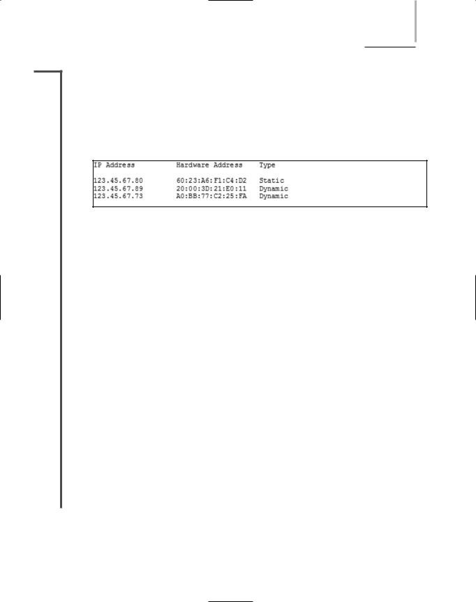
2.10their hard disks in a database known as an ARP table (also called an ARP cache). After a computer has saved this information, the next time it needs the MAC address for another device, it will find the address in its ARP table and will not need to broadcast another request. Although the precise format of ARP tables may vary from one operating system to another, the essential contents of the table and its purpose remain the same. An example ARP table might look like the following:
FIGURE 4-7 Example ARP table
An ARP table can contain two types of entries: dynamic and static. Dynamic ARP table entries are created when a client makes an ARP request that cannot be satisfied by data already in the ARP table. Static ARP table entries are those that someone has entered manually using the ARP utility. The ARP utility, accessed via the arp command from a Windows command prompt or a UNIX or Linux shell prompt, provides a way of obtaining information from and manipulating a device’s ARP table. For example, you can view a Windows XP workstation’s ARP table by typing arp -a and pressing Enter. ARP can be a valuable troubleshooting tool for discovering the identity of a machine whose IP address you know, or for identifying the problem of two machines trying to use the same IP address.
RARP (Reverse Address Resolution Protocol)
If a device doesn’t know its own IP address it cannot use ARP. This is because without an IP address, a device cannot issue an ARP request or receive an ARP reply. One solution to this problem is to allow the client to send a broadcast message with its MAC address and receive an IP address in reply. This process, which is the reverse of ARP, is made possible by RARP (Reverse Address Resolution Protocol). A RARP server maintains a table of MAC addresses and their associated IP addresses (similar to an ARP table). After the RARP server receives the client’s request, it consults the RARP table to find the IP address that matches the client’s MAC address. The RARP server then transmits the IP address information to the client.
RARP was originally developed as a means for diskless workstations—workstations that do not contain hard disks, but rely on a small amount of read-only memory to connect to a net- work—to obtain IP addresses from a server before more sophisticated protocols emerged to perform this function.
148 Chapter 4 NETWORK PROTOCOLS
NET+ Addressing in TCP/IP
2.4You have learned that networks recognize two kinds of addresses: logical (or Network layer) and physical (or MAC, or hardware) addresses. MAC addresses are assigned to a device’s network interface card at the factory by its manufacturer. Logical addresses can be manually or automatically assigned and must follow rules set by the protocol standards. In the TCP/IP protocol suite, IP is the core protocol responsible for logical addressing. For this reason, addresses on TCP/IP-based networks are often called IP addresses. IP addresses are assigned and used according to very specific parameters.
NET+ |
Each IP address is a unique 32-bit number, divided into four octets, or sets of 8-bits, that are |
2.4separated by periods. (Because 8 bits equals a byte, each octet is a byte and an IP address is
2.5thus composed of 4 bytes.) An example of a valid IP address is 144.92.43.178. An IP address
2.6contains two types of information: network and host. From the first octet you can determine the network class. Three types of network classes are used on modern LANs: Class A, Class B, and Class C. Table 4-1 summarizes characteristics of the three commonly used classes of TCP/IP-based networks.
Table 4-1 |
Commonly used TCP/IP classes |
|
|
Network |
Beginning |
Number of |
Maximum Addressable |
Class |
Octet |
Networks |
Hosts per Network |
|
|
|
|
A |
1–126 |
126 |
16,777,214 |
B |
128–191 |
>16,000 |
65,534 |
C |
192–223 |
>2,000,000 |
254 |
|
|
|
|
In addition, Class D and Class E addresses do exist, but are rarely used. Class D addresses, which begin with an octet whose value is between 224 and 239, are reserved for a special type of transmission called multicasting. IETF (Internet Engineering Task Force) reserves Class E addresses, which begin with an octet whose value is between 240 and 254, for experimental use. You should never assign Class D or Class E addresses to devices on your network.
Although 8 bits have 256 possible combinations, only the numbers 1 through 254 can be used to identify networks and hosts in an IP address. The number 0 is reserved to act as a placeholder when referring to an entire group of computers on a network—for example, “10.0.0.0” represents all of the devices whose first octet is “10.” The number 255 is reserved for broadcast transmissions. For example, sending a message to the address 255.255.255.255 will send a message to all devices connected to your network segment.
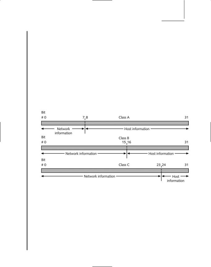
A portion of each IP address contains clues about the network class. An IP address whose first octet is in the range of 1-126 belongs to a Class A network. All IP addresses for devices on a Class A segment share the same first octet, or bits 0 through 7, as shown in Figure 4-8. For example, nodes with the following IP addresses may belong to the same Class A network: 23.78.110.109, 23.164.32.97, 23.48.112.43, and 23.108.37.22. In this example, “23” is the
TCP/IP |
Chapter 4 149 |
NET+ |
network ID. The second through fourth octets (bits 8 through 31) in a Class A address iden- |
2.4tify the host.
2.5An IP whose first octet is in the range of 128-191 belongs to a Class B network. All IP
2.6addresses for devices on a Class B segment share the first two octets, or bits 0 through 15. For example, nodes with the following IP addresses may belong to the same Class B network: 168.34.88.29, 168.34.55.41, 168.34.73.49, and 168.34.205.113. In this example, “168.34” is the network ID. The third and fourth octets (bits 16 through 31) on a Class B network identify the host, as shown in Figure 4-8.
An IP address whose first octet is in the range of 192-223 belongs to a Class C network. All IP addresses for devices on a Class C segment share the first three octets, or bits 0 through 23. For example, nodes with the following addresses may belong to the same Class C network: 204.139.118.7, 204.139.118.54, 204.139.118.14, and 204.139.118.31. In this example, “204.139.118” is the network ID. The fourth octet (bits 24 through 31) on a Class C network identifies the host, as shown in Figure 4-8.
FIGURE 4-8 IP addresses and their classes
Internet founders intended the use of network classes to provide easy organization and a sufficient quantity of IP addresses on the Internet. However, their goals haven’t necessarily been met. Class A addresses were distributed liberally to large companies and government organizations who were early users of the Internet—for example, IBM. Some organizations reserved many more addresses than they had devices. Class B addresses were distributed to mid-sized organizations and Class C addresses to smaller organizations, such as colleges. Today, many Internet addresses go unused, but cannot be reassigned, because an organization has reserved them. And although potentially more than 4.3 billion Internet addresses are available, the demand for such addresses grows exponentially every year. To respond to this demand, a new addressing scheme has been developed that can supply the world with enough addresses to last well into the twenty-first century. IP version 6 (IPv6), also known as the next-generation IP,
150 |
|
|
Chapter 4 NETWORK PROTOCOLS |
|
|
||||
|
|
|
|
|
|
|
will incorporate this new addressing scheme. However, because the switch to a new IP address- |
||
NET+ |
|
|
||
2.4ing scheme will cost billions of dollars in new hardware, software, and training, most organi-
2.5zations are resisting the change.
2.6In addition, some IP addresses are reserved for special functions, like broadcasts, and cannot be assigned to machines or devices. Notice that 127 is not a valid first octet for any IP address. The range of addresses beginning with 127 is reserved for a device communicating with itself, or performing loopback communication. Thus, the IP address 127.0.0.1 is called a loopback address. Attempting to contact this IP number—in other words, attempting to contact your own machine—is known as a loopback test. (In fact, when you transmit to any IP address beginning with the “127” octet you are communicating with your own machine.) A loopback test can prove useful when troubleshooting problems with a workstation’s TCP/IP communications. If you receive a positive response from a loopback test, you know that the TCP/IP core protocols are installed and in use on your workstation.
NET+ |
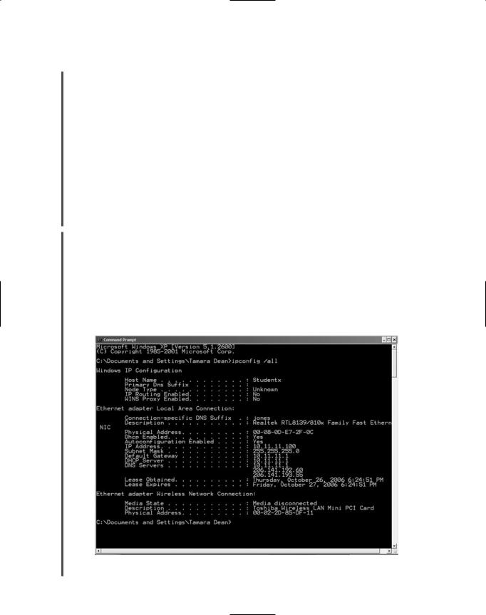
The command used to view IP information on a Windows XP workstation is ipconfig. To |
4.1view your current IP information on a Windows XP workstation:
4.21. Click Start, point to All Programs, point to Accessories, then click Command
Prompt. The Command Prompt window opens.
2.At the command prompt, type ipconfig /all and press Enter. Your workstation’s IP address information is displayed, similar to the information shown in Figure 4-9.
3.Type exit and press Enter to close the Command Prompt window.
FIGURE 4-9 Results of the ipconfig /all command on Windows XP workstation
TCP/IP |
Chapter 4 151 |
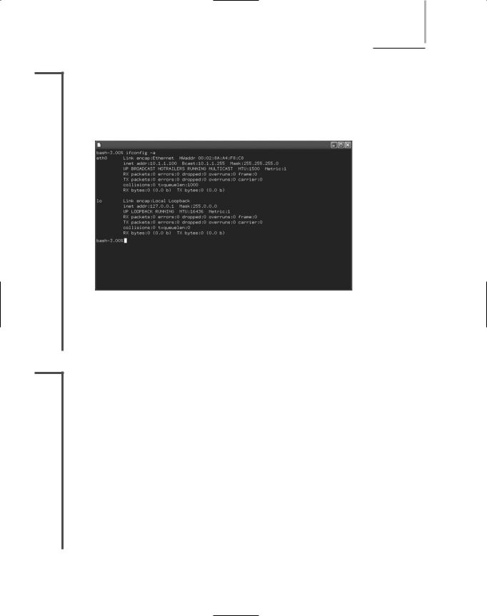
NET+ To view and edit IP information on a computer running a version of the UNIX or Linux oper-
4.1ating system, use the ifconfig command. (Note that ipconfig and ifconfig differ by only
4.2one letter.) Simply type ifconfig -a at the shell prompt to view all the information about your TCP/IP connections and addresses, as shown in Figure 4-10. Note that in this figure, the IP address is labeled “inet addr.”
FIGURE 4-10 Results of the ifconfig –a command on a UNIX workstation
Now that you have learned the most important characteristics of IP addresses, you are ready to learn more about how computers interpret these addresses.
NET+ Binary and Dotted Decimal Notation
2.5So far all of the IP addresses in this section have been represented in dotted decimal notation. Dotted decimal notation, the most common way of expressing IP addresses, refers to the “shorthand” convention used to represent IP addresses and make them easy for people to read. In dotted decimal notation, a decimal number between 0 and 255 represents each binary octet (for a total of 256 possibilities). A period, or dot, separates each decimal. An example of a dotted decimal IP address is 131.65.10.18.
Each number in a dotted decimal address has a binary equivalent. In Chapter 3 you learned how to convert decimal numbers to their binary equivalents. Converting a dotted decimal address to its binary equivalent is simply a matter of converting each octet and removing the decimal points. For example, in the dotted decimal address 131.65.10.18, the binary equivalent of the first octet, “131,” is 10000011, the binary equivalent of the second octet, “65,” is 01000001, the binary equivalent of the third octet, “10,” is 00001010, and the binary equivalent of the fourth octet, “18,” is 00100100. Therefore, the binary value for 131.65.10.18 is 10000011 01000001 00001010 00100100.