

Network Plus 2005 In Depth
.pdf312 |
|
Chapter 7 WANS, INTERNET ACCESS, AND REMOTE CONNECTIVITY |
|
|
|||
|
|
|
|
|
|
one way a router with an integrated CSU/DSU can be used to connect a LAN with a T1 |
|
NET+ |
|
||
1.6 |
|
WAN link. |
|
2.14 |
|
|
|
DSL
NET+ |
DSL (digital subscriber line) is a WAN connection method introduced by researchers at Bell |
2.15Laboratories in the mid-1990s. It operates over the PSTN and competes directly with ISDN and T1 services. Like ISDN, DSL can span only limited distances without the help of repeaters and is therefore best suited to the local loop portion of a WAN link. Also, like its competitors, DSL can support multiple data and voice channels over a single line.
DSL uses advanced data modulation techniques (which are Physical layer functions) to achieve extraordinary throughput over regular telephone lines. To understand how DSL and voice signals can share the same line, it’s helpful to recall that telephone lines carry voice signals over a very small range of frequencies, between 300 and 3300 Hz. This leaves higher, inaudible frequencies unused and available for carrying data. Also recall that in data modulation, a data signal alters the properties of a carrier signal. Depending on its version, DSL connection may use a modulation technique based on amplitude or phase modulation. However, in DSL, modulation follows more complex patterns than the modulation you learned about earlier in this book. The details of DSL modulation techniques are beyond the scope of this book. However, you should understand that the types of modulation used by a DSL version affect its throughput and the distance its signals can travel before requiring a repeater. The following section describes the different versions of DSL.
Types of DSL
The term xDSL refers to all DSL varieties, of which at least eight currently exist. The bet- ter-known DSL varieties include ADSL (asymmetric DSL), G.Lite (a version of ADSL), HDSL (High Bit-Rate DSL), SDSL (Symmetric or Single-Line DSL), VDSL (Very High Bit-Rate DSL), and SHDSL (Single-Line High Bit-Rate DSL)—the “x” in “xDSL” is replaced by the variety name. DSL types can be divided into two categories: asymmetrical and symmetrical.
To understand the difference between these two categories, you must understand the concepts of downstream and upstream data transmission. The term downstream refers to data traveling from the carrier’s switching facility to the customer. Upstream refers to data traveling from the customer to the carrier’s switching facility. In some types of DSL, the throughput rates for downstream and upstream traffic differ. That is, if you were connected to the Internet via a DSL link, you would be able to download images from the Internet more rapidly than you could send them because the downstream throughput would be greater. A technology that offers more throughput in one direction than in the other is considered asymmetrical. In asymmetrical communications, downstream throughput is higher than upstream throughput. Asymmetrical communication is well suited to users who receive more information from the network than they send to it—for example, people watching videoconferences or people surfing the Web. ADSL and VDSL are examples of asymmetrical DSL.
|
DSL |
Chapter 7 313 |
NET+ |
Conversely, symmetrical technology provides equal capacity for data traveling both upstream |
|
2.15and downstream. Symmetrical transmission is suited to users who both upload and download significant amounts of data—for example, a bank’s branch office, which sends large volumes of account information to the central server at the bank’s headquarters and, in turn, receives large amounts of account information from the central server at the bank’s headquarters. HDSL, SDSL, and SHDSL are examples of symmetrical DSL.
DSL versions also differ in the type of modulation they use. Some, such as the popular fullrate ADSL and VDSL, create multiple narrow channels in the higher frequency range to carry more data. For these versions, a splitter must be installed at the carrier and at the customer’s premises to separate the data signal from the voice signal before it reaches the terminal equipment (for example, the phone or the computer). G.Lite, a slower and less expensive version of ADSL, eliminates the splitter but requires the use of a filter to prevent high frequency DSL signals from reaching the telephone. Other types of DSL, such as HDSL and SDSL, cannot use the same wire pair that is used for voice signals. Instead, these types of DSL use the extra pair of wires contained in a telephone cable (that are otherwise typically unused).
The types of DSL also vary in terms of their capacity and maximum line length. A VDSL line that carries as much as 52 Mbps in one direction and as much as 6.4 Mbps in the opposite direction can extend only a maximum of 1000 feet between the customer’s premises and the carrier’s switching facility. This limitation might suit businesses located close to a telephone company’s central office (for example, in the middle of a metropolitan area), but it won’t work for most individuals. The most popular form of DSL, ADSL, provides a maximum of 8 Mbps downstream and a maximum of 1.544 Mbps upstream. However, the distance between the customer and the central office affects the actual throughput a customer will experience. Close to the central office, DSL achieves its highest maximum throughput. The farther away the customer’s premises, the lower the throughput. In the case of ADSL, a customer 9000 feet from the central office can potentially experience ADSL’s maximum potential throughput of 8 Mbps downstream. At 18,000 feet away, the farthest allowable distance, the customer will experience as little as 1.544-Mbps throughput. Still, this throughput and this distance (approximately 3.4 miles) renders ADSL suitable for most telecommuters. Table 7-2 compares current specifications for six DSL types.
Table 7-2 Comparison of DSL types
|
Maximum Upstream |
Maximum Downstream |
Distance |
DSL Type |
Throughput (Mbps) |
Throughput (Mbps) |
Limitation (Feet) |
|
|
|
|
ADSL “full rate”) |
1 |
8 |
18,000 |
G.Lite (a type of ADSL) |
0.512 |
1.544 |
25,000 |
HDSL or HDSL-2 |
1.544 or 2.048 |
1.544 or 2.048 |
18,000 or 12,000 |
SDSL |
1.544 |
1.544 |
12,000 |
SHDSL |
2.36 or 4.7 |
2.36 or 4.7 |
26,000 or 18,000 |
VDSL |
1.6, 3.2, or 6.4 |
12.9, 25.9, or 51.8 |
1000–4500 |
|
|
|
|
314 Chapter 7 WANS, INTERNET ACCESS, AND REMOTE CONNECTIVITY
NET+
2.15
NOTE
Published distance limitations and throughput can vary from one service provider to another, depending on how far the provider is willing to guarantee a particular level of service.
In addition to their data modulation techniques, capacity, and distance limitations, DSL types vary according to how they use the PSTN. Next, you will learn about how DSL connects to a business or residence over the PSTN.
DSL Connectivity
This section follows the path of an ADSL connection from a home computer, through the local loop, and to the telecommunications carrier’s switching facility. Although variations exist, this describes the most common implementation of DSL.
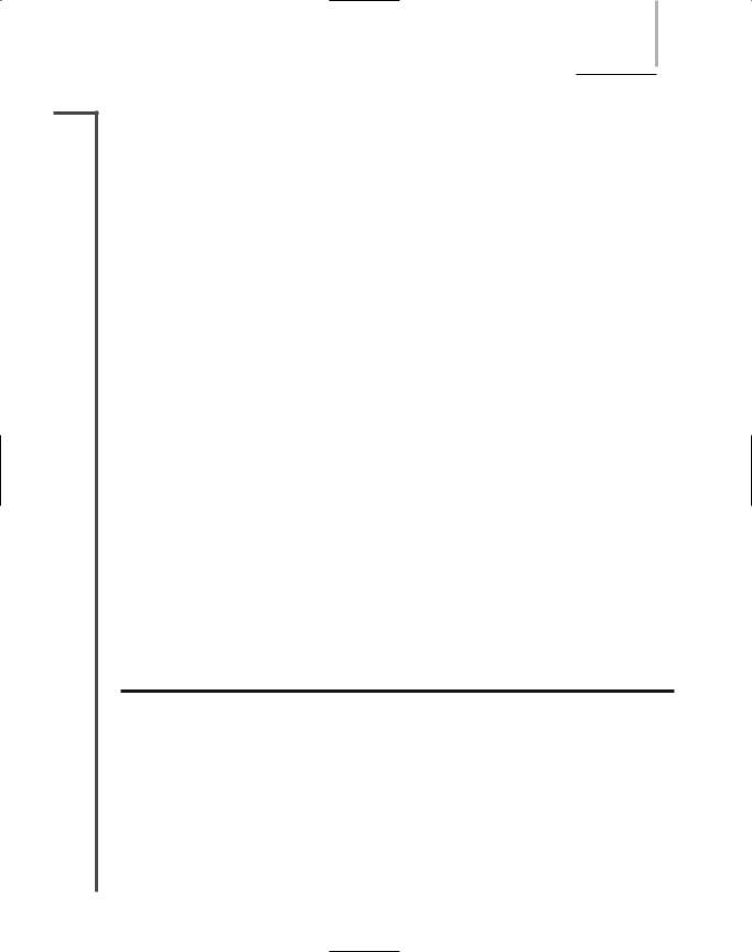
Suppose you have an ADSL connection at home. One evening you open your Web browser and request the home page of your favorite sports team to find the last game’s score. As you know, the first step in this process is establishing a TCP connection with the team’s Web server. Your TCP request message leaves your computer’s NIC and travels over your home network to a DSL modem. A DSL modem is a device that modulates outgoing signals and demodulates incoming DSL signals. Thus, it contains receptacles to connect both to your incoming telephone line and to your computer or network connectivity device. Because you’re using ADSL, the DSL modem also contains a splitter to separate incoming voice and data signals. The DSL modem may be external to the computer and connect to a computer’s Ethernet NIC via an RJ-45, USB, or wireless interface. If your home network contains more than one computer and you want all computers to share the DSL bandwidth, the DSL modem must connect to a device such as a hub, switch, or router, instead of just one computer. In fact, rather than using two separate devices, you could buy a router that combines DSL modem functionalities with the ability to connect multiple computers and share DSL bandwidth. A DSL modem is shown in Figure 7-14.
FIGURE 7-14 A DSL modem
DSL |
Chapter 7 315 |
NET+ When your request arrives at the DSL modem, it is modulated according to the ADSL spec-
2.15ifications. Then the DSL modem forwards the modulated signal to your local loop—the lines that connect your home with the rest of the PSTN. For the first stretch of the local loop, the signal continues over four-pair UTP wire. At some distance less than 18,000 feet, it is combined with other modulated signals in a telephone switch. If this switch is not in a central office, it forwards your request—this time over fiber-optic cable or a high-speed wireless link—to another switch at the central office. (To accept DSL signals, your telecommunications carrier must have newer digital switching equipment. In areas of the country where carriers have not updated their switching equipment, DSL service is not available.)
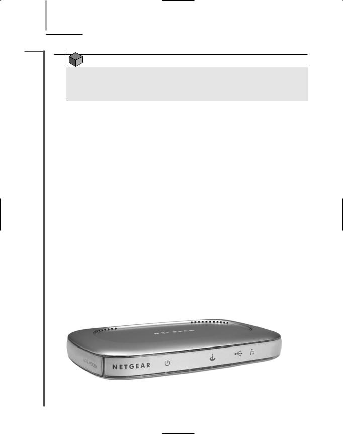
Inside the carrier’s switching facility, a splitter separates your line’s data signal (the TCP request) from any voice signals that are also carried on the line. Next, your request is sent to a device called a DSLAM (DSL access multiplexer), which aggregates multiple DSL subscriber lines and connects them to a larger carrier or to the Internet backbone, as pictured in Figure 7-15. The request travels over the Internet until it reaches your sports team’s Web server. Barring line problems and Internet congestion, the entire journey happens in a fraction of a second. After your team’s Web server accepts the connection request, the data follows the same path, but in reverse.
FIGURE 7-15 A DSL connection

316 |
|
|
Chapter 7 WANS, INTERNET ACCESS, AND REMOTE CONNECTIVITY |
|
|
||||
|
|
|
|
|
|
|
Currently, ADSL is the most common form of DSL, but standards continue to evolve. |
||
NET+ |
|
|
||
2.15Telecommunications carriers and manufacturers have positioned DSL as a competitor for T1, ISDN, and broadband cable services. The installation, hardware, and monthly access costs for DSL are slightly less than those for ISDN lines and significantly less than the cost for T1s. (At the time of this writing, ADSL costs approximately $30 per month in the United States.) Considering that DSL technology can provide faster throughput than T1s, it presents a formidable challenge to T-carrier services for business customers.
One drawback to DSL is that it is not available in all areas of the United States, either because carriers have not upgraded their switching equipment or because customers do not reside within the service’s distance limitations. In addition, in its early years DSL was more expensive than broadband cable, its main competition among residential customers. For these reasons, twothirds of consumers in the United States use cable for broadband Internet access service.
Broadband Cable
NET+ |
While local and long-distance phone companies strive to make DSL the preferred method of |
2.15Internet access for consumers, cable companies are pushing their own connectivity option. This option, called broadband cable or cable modem access, is based on the coaxial cable wiring used for TV signals. Such wiring can theoretically transmit as much as 56 Mbps downstream and as much as 10 Mbps upstream. Thus, broadband cable is an asymmetrical technology. Realistically, however, broadband cable throughput is limited (or throttled) by the cable companies, so that customers are allowed, at most, 3-Mbps downstream and 1-Mbps upstream throughput. The asymmetry of broadband cable makes it a logical choice for users who want to surf the Web or download data from a network. Some companies are also delivering music, videoconferencing, and Internet services over cable infrastructure.
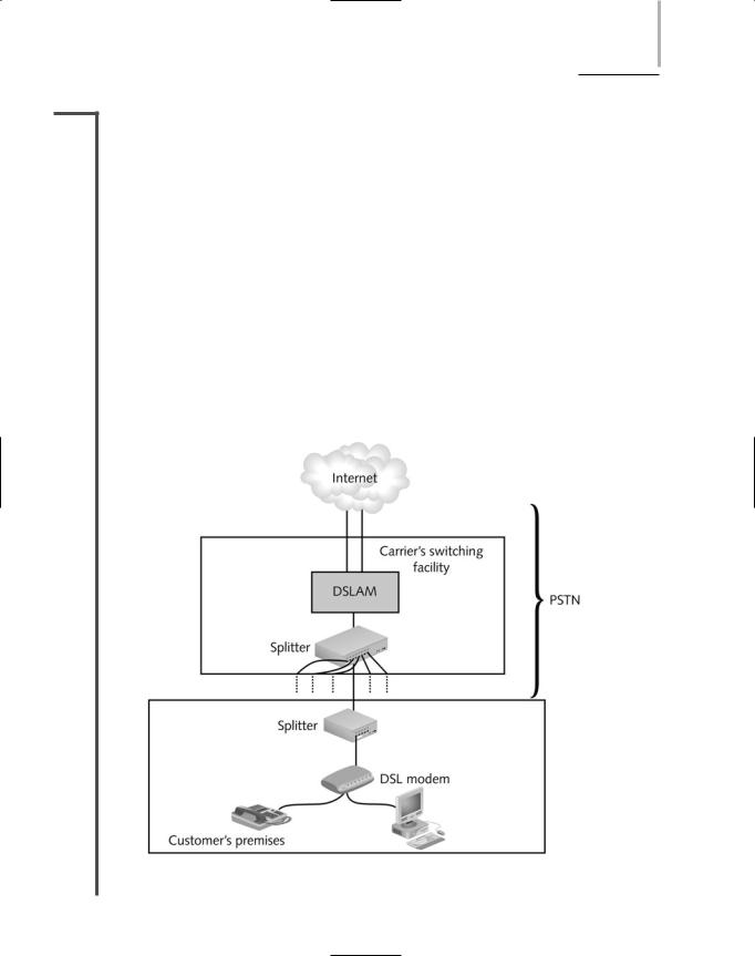
Broadband cable connections require that the customer use a special cable modem, a device that modulates and demodulates signals for transmission and reception via cable wiring. Cable modems operate at the Physical and Data Link layer of the OSI Model, and therefore do not manipulate higher-layer protocols such as IP or IPX. The cable modem then connects to a customer’s PC via an RJ-45, USB, or wireless interface to a NIC. Alternately, the cable modem could connect to a connectivity device, such as a hub, switch, or router, thereby supplying bandwidth to a LAN rather than to just one computer. It’s also possible to use a device that combines cable modem functionality with a router; this single device can then provide both the broadband cable connection and the capability of sharing the bandwidth between multiple nodes. Figure 7-16 provides an example of a cable modem.
Before customers can subscribe to broadband cable, however, their local cable company must have the necessary infrastructure. Traditional cable TV networks supply the infrastructure for downstream communication (the TV programming), but not for upstream communication. To provide Internet access through its network, the cable company must upgrade its existing equipment to support bidirectional, digital communications. For starters, the cable company’s network wiring must be replaced with HFC (hybrid fiber-coax), an expensive fiber-optic link that
BROADBAND CABLE |
Chapter 7 317 |
NET+
2.15
FIGURE 7-16 A cable modem
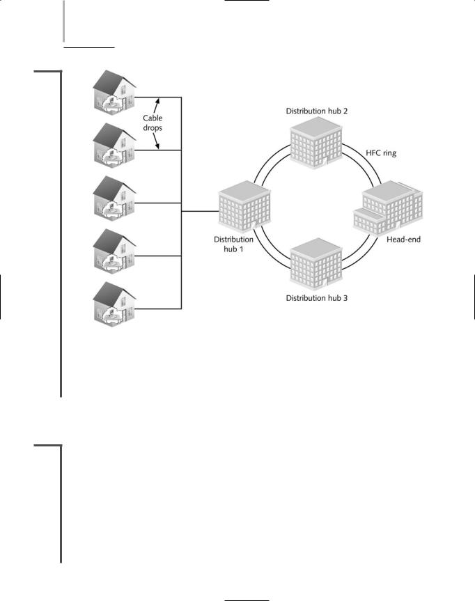
can support high frequencies. The HFC connects the cable company’s offices to a node location near the customer. Most large cable companies, such as Comcast and Charter, long ago upgraded their infrastructure to use HFC. Either fiber-optic or coaxial cable may connect the node to the customer’s business or residence via a connection known as a cable drop. All cable drops for the cable subscribers in the same neighborhood connect to the local node. These nodes then connect to the cable company’s central office, which is known as its head-end. At the head-end, the cable company can connect to the Internet through a variety of means (often via fiber-optic cable) or it can pick up digital satellite or microwave transmissions. The head-end can transmit data to as many as 1000 subscribers, in a one-to-many communication system. Figure 7-17 illustrates the infrastructure of a cable system.
Like DSL, broadband cable provides a dedicated, or continuous, connection that does not require dialing up a service provider. Unlike DSL, broadband cable requires many subscribers to share the same local line, thus raising concerns about security and actual (versus theoretical) throughput. For example, if your cable company supplied you and five of your neighbors with broadband cable services, your neighbors could, with some technical prowess, capture the data that you transmit to the Internet. (Modern cable networks provide encryption for data traveling to and from customer premises; however, these encryption schemes can be readily thwarted.) Moreover, the throughput of a cable line is fixed. As with any fixed resource, the more one claims, the less that is left for others. In other words, the greater the number of users sharing a single line, the less throughput available to each individual user. Cable companies counter this perceived disadvantage by rightly claiming that at some point (for example, at a remote switching facility or at the DSLAM interface), a telecommunications carrier’s DSL bandwidth is also fixed and shared among a group of customers.
As mentioned earlier, cable broadband access continues to service the majority of residential customers, whereas DSL is more popular among business customers. Now, however, since the cost of DSL has decreased, the rate of new DSL and broadband cable installations is nearly identical. In the United States, broadband cable access costs approximately $45 per month for
318 Chapter 7 WANS, INTERNET ACCESS, AND REMOTE CONNECTIVITY
NET+
2.15
FIGURE 7-17 Cable infrastructure
customers who already subscribe to cable TV service. Broadband cable is less often used in businesses than DSL, primarily because most office buildings do not contain a coaxial cable infrastructure.
SONET (Synchronous Optical Network)
NET+ |
SONET (Synchronous Optical Network) is a high-bandwidth WAN signaling technique |
2.14developed by Bell Communications Research in the 1980s, and later standardized by ANSI and ITU. SONET specifies framing and multiplexing techniques at the Physical layer of the OSI Model. Its four key strengths are that it can integrate many other WAN technologies, it offers fast data transfer rates, it allows for simple link additions and removals, and it provides a high degree of fault tolerance. (The word synchronous as used in the name of this technology means that data being transmitted and received by nodes must conform to a timing scheme. A clock maintains time for all nodes on a network. A receiving node in synchronous communications recognizes that it should be receiving data by looking at the time on the clock.)
SONET (SYNCHRONOUS OPTICAL NETWORK) |
Chapter 7 319 |
NET+ Perhaps the most important SONET advantage is that it provides interoperability. Before
2.14SONET, telecommunications carriers that used different signaling techniques (or even the same technique but different equipment) could not be assured that their networks could communicate. Now, SONET is often used to aggregate multiple T1s, T3s, or ISDN lines. SONET is also used as the underlying technology for ATM transmission. Furthermore, because it can work directly with the different standards used in different countries, SONET has emerged as the best choice for linking WANs between North America, Europe, and Asia. Internationally, SONET is known as SDH (Synchronous Digital Hierarchy).
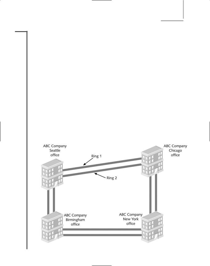
SONET’s extraordinary fault tolerance results from its use of a double-ring topology (similar to FDDI) over fiber-optic cable. In this type of layout, one ring acts as the primary route for data, transmitting in a clockwise direction. The second ring acts as a backup, transmitting data counterclockwise around the ring. If, for example, a backhoe operator severs the primary ring, SONET would automatically reroute traffic to the backup ring without any loss of service. This characteristic, known as self-healing, makes SONET very reliable. (To lower the potential for a single accident to sever both rings, the cables that make up each ring should not lay adjacent to each other.) Figure 7-18 illustrates a SONET ring and its dual-fiber connections.
A SONET ring begins and ends at the telecommunications carrier’s facility. In between, it connects an organization’s multiple WAN sites in a ring fashion. It may also connect with multiple carrier facilities for additional fault tolerance. Companies can lease an entire SONET ring from a telecommunications carrier, or they can lease part of a SONET ring—for example, a circuit that offers T1 throughput—to take advantage of SONET’s reliability.
FIGURE 7-18 A SONET ring
320 |
|
|
Chapter 7 WANS, INTERNET ACCESS, AND REMOTE CONNECTIVITY |
|
|
||||
|
|
|
|
|
|
|
At both the carrier and the customer premises, a SONET ring terminates at a multiplexer. A |
||
NET+ |
|
|
||
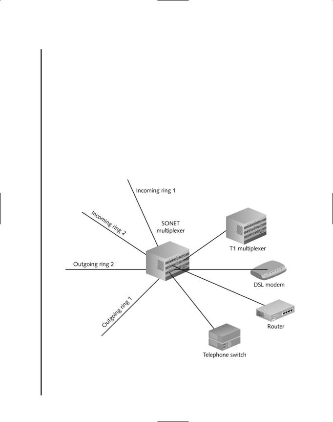
2.14multiplexer combines individual SONET signals on the transmitting end, and another multiplexer separates combined signals on the receiving end. On the transmitting end, multiplexers accept input from different network types (for example, a T1 or ISDN line) and format the data in a standard SONET frame. That means that many different devices might connect to a SONET multiplexer, including, for example, a private telephone switch, a T1 multiplexer, and an ATM data switch. On the receiving end, multiplexers translate the incoming signals back into their original format. Most SONET multiplexers allow for easy additions or removals of connections to the SONET ring, which makes this technology easily adaptable to growing and changing networks. Figure 7-19 shows the devices necessary to connect a WAN site with a SONET ring. This is the simplest type of SONET connection; however, variations abound.
The data rate of a particular SONET ring is indicated by its OC (Optical Carrier) level, a rating that is internationally recognized by networking professionals and standards organizations. OC levels in SONET are analogous to the digital signal levels of T1s. Table 7-3 lists the OC levels and their maximum throughput.
FIGURE 7-19 SONET connectivity

WIRELESS WANS AND INTERNET ACCESS |
Chapter 7 321 |
NET+
2.14
Table 7-3 |
SONET OC levels |
OC Level |
Throughput (Mbps) |
|
|
OC1 |
51.84 |
OC3 |
155.52 |
OC12 |
622 |
OC24 |
1244 |
OC48 |
2480 |
OC96 |
4976 |
OC192 |
9953 |
OC768 |
39813 |
|
|
SONET technology is typically not implemented by small or medium-sized businesses, because of its high cost. It is more commonly used by large global companies, long-distance companies linking metropolitan areas and countries, or ISPs that want to guarantee fast, reliable access to the Internet. SONET is particularly suited to audio, video, and imaging data transmission. As you can imagine, given its reliance on fiber-optic cable and its redundancy requirements, SONET technology is expensive to implement.
Wireless WANs and Internet Access
NET+ |
Wireless WANs can be created using many types of transmission technologies. Some of the |
2.15oldest technologies were developed by telephone companies to provide their customers with an alternative to wire-bound local loops. Other wireless WANs use another technology from the twentieth century—satellite transmission—which was originally developed for TV and radio broadcasts. But the latest wireless WAN technologies, collectively known as wireless broadband, are designed specifically for high-throughput, long-distance digital data exchange. The following sections describe a variety of ways wireless clients can access the Internet.
IEEE 802.11 Internet Access
In Chapter 6, you learned how LANs can be created using the IEEE 802.11b (“Wi-Fi”), 802.11a, or 802.11g wireless technology. Wireless access points are also used by airports, libraries, universities, hotels, cafés and restaurants to provide customers or visitors with wireless Internet access. Currently, most use the 802.11b access method. Places where wireless Internet access is available to the public are called hot spots. Some organizations, such as T- Mobile, have established a network of hot spots across the nation. Other organizations, such as a local coffee shop, might have only one hot spot. In some cases, Internet access is free. In