

9-12 ELECTRICAL SYSTEM
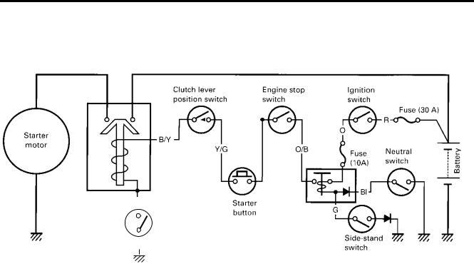
STARTER SYSTEM AND SIDE-STAND/IGNITION INTERLOCK SYSTEM
2) Pull the clutch lever, turn on the ignition switch with the engine stop switch in the “RUN” position and lis-
|
|
|
|
|
|
|
|
|
|
|
|
|
|
|
|
|
|
|
|
|
|
|
|
|
|
|
|
|
|
|
|
|
|
|
|
|
|
|
|
|
|
|
|
|
|
|
|
|
|
|
|
|
|
|
|
|
|
|
|
|
|
|
|
|
Engine stop |
|
|
|
|
|
|
|
Ignition |
|
|
|
|
|
|
|
|
|
|
|
|||||
|
|
|
|
|
|
|
|
|
|
|
|
|
|
|
|
|
|
|
|
switch |
|
|
|
|
|
|
|
switch |
|
|
|
|
|
|
|
|
|
|
|
|||||
|
|
|
|
|
|
|
|
To Ignition |
|
|
|
O/W |
|
|
|
|
|
|
|
|
|
|
|
|
|
|
|
|
|
Fuse (30 A) |
|
|
|
|
|
|||||||||
|
|
|
|
|
|
|
|
|
|
|
|
|
|
|
|
|
|
|
|
|
|
|
|
|
|
|
|
|
|
|
|
|
|
|
|
|||||||||
|
|
|
|
|
|
|
|
|
|
|
|
|
|
|
|
|
|
|
|
|
|
|
|
|
|
|
|
R |
|
|
|
|
|
|
|
|
||||||||
|
|
|
|
|
|
|
|
coil |
|
|
|
|
|
|
|
|
|
|
|
|
|
|
|
|
|
|
|
|
|
|
|
|
|
|||||||||||
|
|
|
|
|
|
|
|
|
|
|
|
|
|
|
|
|
|
|
|
|
|
|
|
|
|
|
|
|
|
|
||||||||||||||
|
|
|
|
|
|
|
|
|
|
|
|
|
|
|
|
|
|
|
|
|
|
|
|
|
|
|
|
|
|
|
|
|
|
|
|
|
|
|
||||||
|
|
|
|
|
|
|
|
|
|
|
|
|
|
|
|
|
|
|
|
|
|
|
|
|
|
|
|
|
|
|
|
|
|
|
|
|
|
|
||||||
|
Starter |
|
|
|
|
|
|
|
Y/G |
|
|
|
|
|
|
|
|
|
|
|
|
|
|
|
|
|
|
|
|
|
|
|
|
|
|
|
|
|
|
|
|
|
|
|
|
|
|
|
|
|
|
|
|
|
|
|
|
|
|
|
|
|
|
|
|
|
|
|
|
|
|
|
|
|
|
|
|
|
|
|
|
|
|
|
|
|
|
||
|
motor |
|
|
|
|
|
|
|
|
|
|
|
|
|
|
|
|
|
|
|
|
O/B |
|
|
|
|
|
|
Fuse |
GP switch |
|
|
|
|
|
|
||||||||
|
|
|
|
|
|
|
|
|
|
|
|
|
|
|
|
|
|
|
|
|
|
|
|
|
|
|
|
|
|
|
|
|
|
|||||||||||
|
|
|
|
|
|
|
|
|
|
|
|
|
|
|
|
|
|
|
|
|
|
|
|
|
|
|
|
|
|
|
|
|
|
|
|
|||||||||
|
|
|
|
|
|
|
|
|
|
|
|
|
|
|
|
|
|
|
|
|
|
|
|
|
|
|
|
|
||||||||||||||||
|
|
|
|
|
|
|
|
|
|
|
|
|
|
|
|
|
|
|
|
|
|
|
|
|
|
|
|
|
|
(10 A) |
(Neutral) |
|
|
|
Battery |
|
||||||||
|
|
|
|
|
|
|
|
|
|
|
|
|
|
|
|
|
|
|
|
|
|
|
|
|
|
|
|
|
|
|
|
|
|
|
|
|
|
|
|
|
|
|
|
|
|
|
|
|
|
|
|
|
|
|
|
|
|
|
|
|
|
|
|
|
|
|
|
|
|
|
|
|
|
|
|
|
|
|
|
|
|
|
|
|
|
|
|
|
|
|
|
Starter relay |
|
|
|
|
|
|
|
|
|
|
|
|
|
|
|
|
|
|
|
|
|
|
|
|
|
|
|
|
Bl |
|
|
|
|
|
|
|
|
|
|
|
|
|
|
|
|
|
|
|
|
|
|
|
|
|
|
|
|
|
|
|
|
|
|
|
|
|
|
|
|
|
|
|
|
|
|
|
|
|
|
|
|
|
|
|
|
|
|
|
|
|
B/Y |
|
|
|
|
|
|
|
|
Starter |
|
|
|
Turn signal/ |
|
|
|
|
|
|
|
|
|
|
|
|
|
|
|
|
|
|
|
|
||||||||
|
|
|
|
|
|
|
|
|
|
|
|
|
|
|
|
|
|
|
|
|
|
|
|
|
|
|
|
|
|
|
|
|
|
|
||||||||||
|
|
|
|
|
|
|
|
|
|
|
|
|
|
button |
|
|
|
|
G |
|
|
|
|
|
|
|
|
|
|
|
|
|
|
|
|
|
||||||||
|
|
|
|
|
|
|
|
|
|
|
|
|
|
|
|
|
side-stand relay |
|
|
|
|
|
|
|
|
|
|
|||||||||||||||||
|
|
|
|
|
|
|
|
|
|
|
|
|
|
|
|
|
|
|
|
|
|
|
|
|
|
|
|
|
|
|
||||||||||||||
|
|
|
|
|
|
|
Clutch switch |
|
|
|
|
|
|
|
|
|
|
|
|
|
|
|
||||||||||||||||||||||
|
|
|
|
|
|
|
|
|
|
|
|
|
|
|
|
|
|
|
|
|
|
|
|
|
|
|
|
|
|
|
|
|
|
|
|
|
|
|||||||
|
|
|
|
|
|
|
|
|
|
|
|
|
|
|
|
|
|
|
|
|
|
|
|
|
|
|
|
|
|
|
|
|
|
|
|
|
|
|
|
|
|
|
|
|
|
|
|
|
|
|
|
|
|
|
|
|
|
|
|
|
|
|
|
|
|
|
|
|
|
|
|
|
|
side-stand |
|
|
|
|
|
|
|
|
|
|
|||||
|
|
|
|
B/W |
|
|
|
|
|
|
|
|
|
|
|
|
|
|
|
|
|
|
|
|
|
|
|
|
|
|
|
|
|
|
|
|
|
|||||||
|
|
|
|
|
|
|
|
|
|
|
|
|
|
|
|
|
|
|
|
|
|
|
|
|
|
|
switch |
|
|
|
|
|
|
|
|
|
|
|||||||
|
|
|
|
|
|
|
|
|
|
|
|
|
|
|
|
|
|
|
|
|
|
|
|
|
|
|
|
|
|
|
|
|
|
|
||||||||||
TROUBLESHOOTING |
|
|
|
|
|
|
|
|
|
|
|
|
|
|
|
|
|
E |
|
|
|
|
|
|
|
|
|
|
||||||||||||||||
Make sure that the fuses are not blown and the battery is fully-chargedLbefore diagnosing. |
|
|
|
|
||||||||||||||||||||||||||||||||||||||||
Starter motor will not run |
|
|
|
|
|
|
|
|
|
|
|
|
P |
|
|
|
|
|
|
|
|
|
|
|
|
|
|
|
|
|
|
|
|
|||||||||||
Step 1 |
|
|
|
|
|
|
|
|
|
|
|
|
|
|
|
|
|
|
|
|
|
|
|
|
|
|
|
|
|
|
|
|
||||||||||||
|
|
|
|
|
|
M |
|
|
|
|
|
|
|
|
|
|
|
|
|
|
|
|
|
|
|
|
||||||||||||||||||
1) Shift the transmission to neutral. |
|
|
|
|
|
|
|
|
|
|
|
|
|
|
|
|
|
|
|
|
|
|
|
|||||||||||||||||||||
|
|
|
|
|
|
|
|
|
|
|
|
|
|
|
|
|
|
|
|
|
|
|
|
|
|
|
|
|
|
|||||||||||||||
|
|
|
|
|
|
|
|
A |
|
|
|
|
|
|
|
|
|
|
|
|
|
|
|
|
|
|
|
|
|
|
|
|
|
|
|
|
|
|
|
|||||
|
|
S |
ten for a click from the starter relay when the starter button is pushed. |
||
Is a click sound heard? |
|
|
YES |
Go to Step 2. |
|
|
|
|
NO |
Go to Step 3. |
|
Step 2
1)Check if the starter motor runs when its terminal is connected to the battery + terminal. (Do not use thin “wire” because a large amount of current flows.)
Does the starter motor run?
|
• |
Faulty starter relay |
YES |
• Loose or disconnected starter motor lead wire |
|
|
• |
Loose or disconnected between starter relay and battery + terminal |
NO |
Faulty starter motor |
|
|
|
|
ELECTRICAL SYSTEM 9-13
Step 3
1)Measure the starter relay voltage at the starter relay connectors (between Y/G + and B/Y -) when the starter button is pushed.
Is a voltage OK?
YES |
Go to Step 4. |
|
|
|
|
|
• Faulty engine stop switch |
|
|
• |
Faulty clutch switch |
|
• |
Faulty GP switch |
|
• Faulty turn signal/side-stand relay |
|
NO |
• |
Faulty starter button |
|
• |
Faulty ignition switch |
|
• Faulty side-stand switch |
|
|
• Poor contact of connector |
|
|
• Open circuit in wire harness |
|
|
|
|
1)Check the starter relay. ( 9-16) Is the starter relay OK?
when the transmission is in
Step 2
1)Check the starter clutch. Is the starter clutch OK?
YES |
• |
Open circuit in wire harness |
|
• |
Poor contact of connector |
||
|
|||
|
|
||
NO |
Faulty starter clutch |
||
|
|
|
|
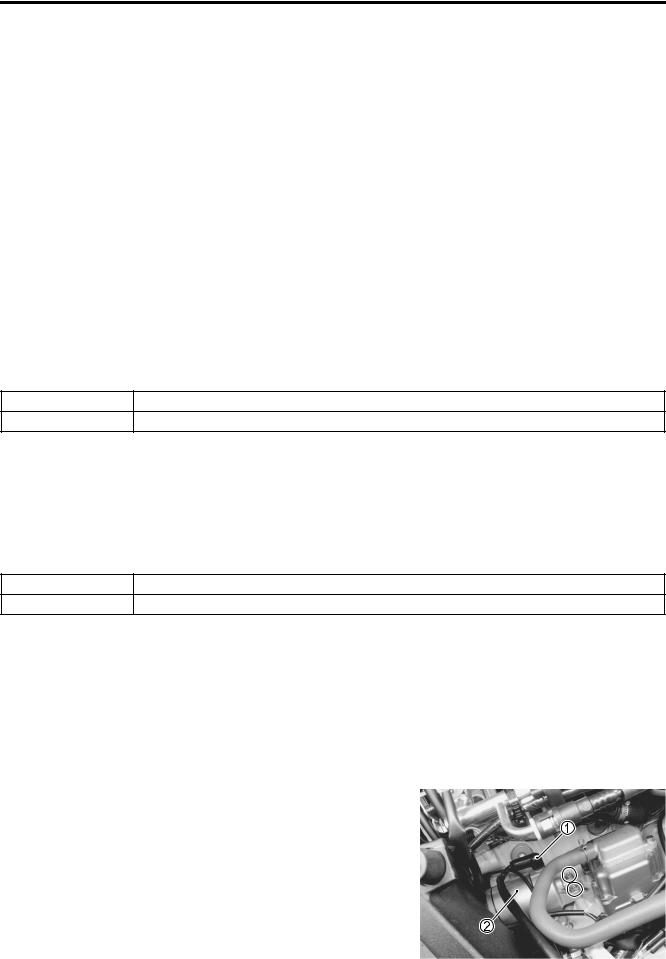
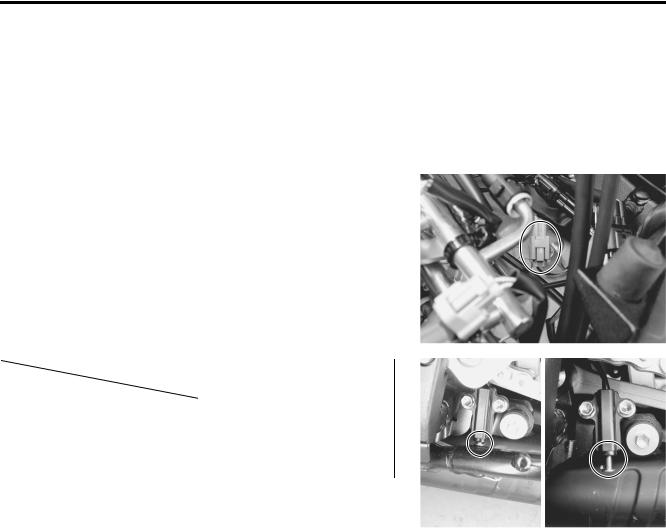
STARTER MOTOR REMOVAL
•Remove the front seat.( 8-7)
•Disconnect the battery - lead wire.
•Lift and support the fuel tank.( 5-3)
•Disconnect the starter motor lead wire 1.
•Remove the starter motor 2.
9-14 ELECTRICAL SYSTEM
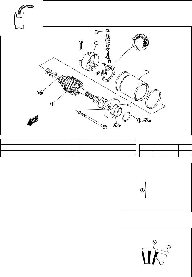
STARTER MOTOR DISASSEMBLY
• Disassemble the starter motor as shown in the illustration.
|
|
|
|
E |
|
|
|
|
|
|
L |
|
|
|
|
1 O-ring |
4 |
Armature |
P |
|
|
|
|
2 Housing end (inside) |
5 |
M |
ITEM |
N·m |
kgf-m |
lb-ft |
|
Housing end (outside) |
|||||||
3 Starter motor case |
A |
|
A |
6 |
0.6 |
4.5 |
|
S |
Lead wire mounting bolt |
||||||
|
|
|
|
|
|
|
|
STARTER MOTOR IN PECTION |
|
|
|
|
|
||
CARBON BRUSH |
|
|
|
|
|
|
|
Inspect the brushes for abnormal wear, cracks, or smoothness |
|
|
|
|
|||
in the brush holder. |
|
|
|
|
|
|
|
If any damages are found, replace the brush assembly with a |
|
|
|
|
|||
new one. |
|
|
|
|
|
|
|
Make sure that the length A is not less than 6.5 mm (0.26 in), If |
|
|
|
|
|||
this length becomes less than 6.5 mm (0.26 in), replace the |
|
|
|
|
|||
brush. |
|
|
|
|
|
|
|
Starter motor brush length |
|
|
|
|
|
|
|
Service Limit: 6.5 mm (0.26 in) |
|
|
|
|
|
|
|
COMMUTATOR
Inspect the commutator for discoloration, abnormal wear or undercut A.
If abnormal wear is found, replace the armature with a new one. If the commutator surface is discolored, polish it with #400 sand paper and wipe it using a clean dry cloth.
If there is no undercut, scrape out the insulator with a saw blade.
1 Insulator
2 Segment
ELECTRICAL SYSTEM 9-15
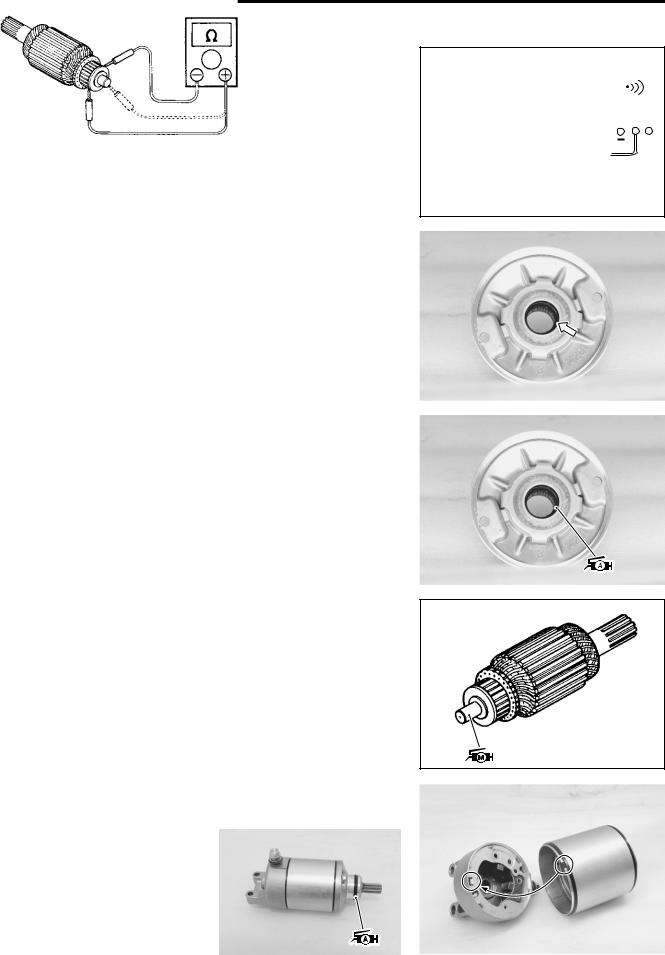
ARMATURE COIL INSPECTION
Check for continuity between each segment and between each segment and the armature shaft using the multi-circuit tester.
If there is no continuity between the segments or there is continuity between the segments and shaft, replace the armature with a new one.
09900-25008: Multi-circuit tester set
Tester knob indication: Continuity test ( )
OIL SEAL INSPECTION
Check the oil seal lip for damage or leakage.
If any damage is found, replace the housing end.
STARTER MOTOR REASSEMBLY |
L |
|
P |
E |
|
Reassemble the starter motor in the reverse order of disassem- |
|
|
bly. Pay attention to the following points: |
|
|
• Apply SUZUKI SUPER GREASE “A” to the lip of the oil seal. |
|
|
99000-25010: SUZUKI SUPER GREASE “A” |
|
|
A |
|
|
M(or equivalent grease) |
|
|
S |
|
|
•Apply a small quantity of SUZUKI MOLY PASTE to the armature shaft.
99000-25140: SUZUKI MOLY PASTE
•Fit the projection of the starter motor case to the depression of the housing end.
•Apply SUZUKI SUPER GREASE to the O-ring.
99000-25010: SUZUKI SUPER GREASE “A”
(or equivalent grease)
9-16 ELECTRICAL SYSTEM
•Tighten the starter motor lead wire mounting bolt to the specified torque.
Lead wire mounting bolt: 6 N·m (0.6 kgf-m, 4.5 lb-ft)
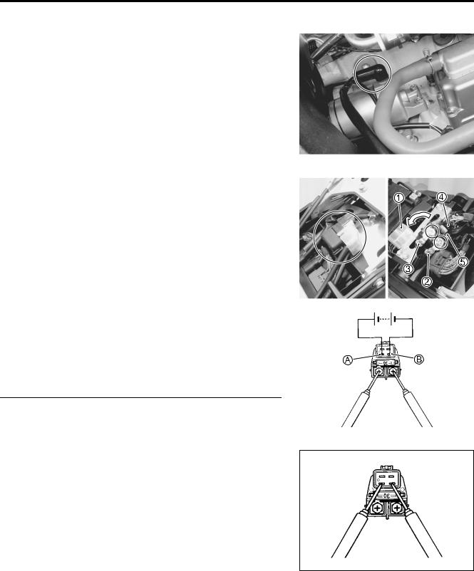
STARTER RELAY INSPECTION
• Remove the front seat. ( 8-7) |
|
|
|
|
|
|
|
|
• Disconnect the battery - lead wire from the battery. |
|
|
|
|
|
|||
• Remove the frame cover. ( 8-8) |
|
|
|
|
|
|
||
• Remove the starter relay cover 1. |
|
|
|
|
|
|
||
• Disconnect the starter motor lead wire 2, battery lead wire 3 |
|
|
|
|||||
and starter relay coupler 4. |
|
|
|
|
|
|
|
|
• Remove the starter relay 5. |
|
|
|
|
|
|
|
|
• Apply 12 V to A and B terminals and check for continuity |
|
|||||||
|
|
|
|
|
|
L |
||
between the positive and negative terminals using the |
|
|
E |
|||||
|
|
|
|
P |
|
|
||
multi-circuit tester. If the starter relay clicks and continuity is |
|
|
|
|||||
found, the relay is ok. |
|
|
M |
|
|
|
||
09900-25008: Multi-circuit tester set |
|
|
|
|||||
|
|
A |
|
|
|
|
|
|
Tester knob indication: Continuity test ( ) |
|
|
|
|
|
|||
|
S |
|
|
|
|
|
|
|
|
|
|
|
|
|
|
||
Do not apply battery voltage to the starter relay for |
|
|
|
|
||||
more than five seconds, since the relay coil may over- |
|
|
|
|
||||
heat and get damaged. |
|
|
|
|
|
|
|
|
|
|
|
|
|
|
|
|
|
|
|
|
|
|
|
|
|
|
Measure the relay coil resistance between the terminals using the multi-circuit tester. If the resistance is not within the specified value, replace the starter relay with a new one.
09900-25008: Multi-circuit tester set
Starter relay resistance: 3 – 6 Ω
ELECTRICAL SYSTEM 9-17
SIDE STAND/IGNITION INTERLOCK SYSTEM PARTS INSPECTION
Check the interlock system for proper operation. If the interlock system does not operate properly, check each component for damage or abnormalities. If any abnormality is found, replace the component with a new one.
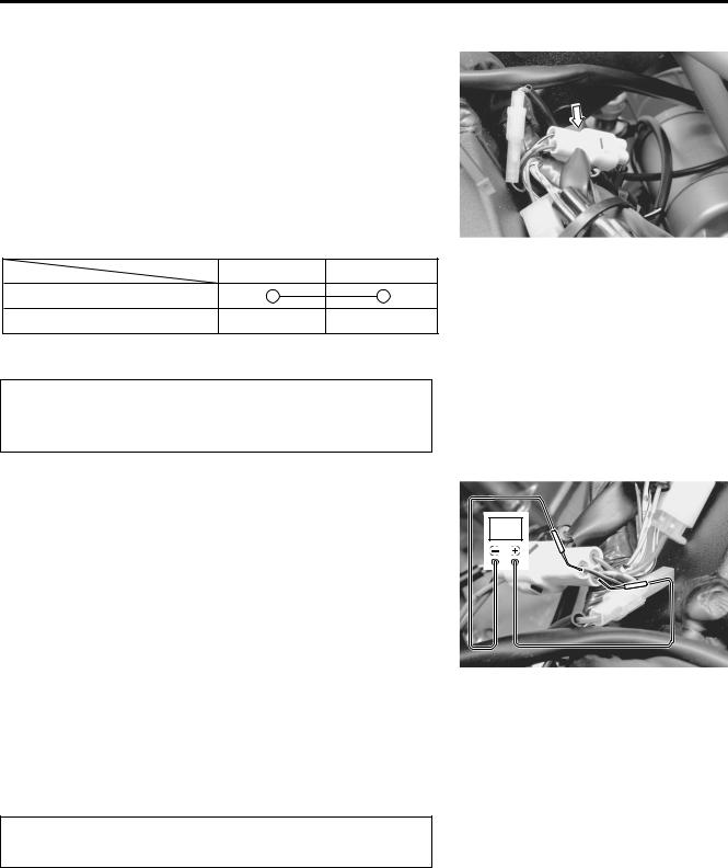
SIDE-STAND SWITCH
The side-stand switch coupler is located above the crankcase.
•Remove the front seat.
•Disconnect the battery - lead wire from the battery.
•Lift and support the fuel tank. ( 5-3)
•Disconnect the side-stand switch coupler and measure the voltage between Green and Black/White lead wires.
09900-25008: Multi-circuit tester set
Tester knob indication: Diode test ( )
|
|
|
Green |
Black/White |
|
E |
|
|
|
|
(+ Probe) |
(- Probe) |
|
||
|
|
|
|
|
|||
|
|
|
|
|
|
|
|
ON |
|
|
0.4 – 0.6 V |
L |
|||
(Side-stand up) |
|
|
|||||
|
|
|
|
|
|||
|
|
|
|
|
|
|
|
|
|
|
|
|
|
|
|
OFF |
|
|
|
P |
|
||
|
|
1.4 V and more |
|
|
|
||
(Side-stand down) |
|
|
(Tester’s battery voltage) |
|
|||
NOTE: |
|
|
M |
|
|
|
|
|
|
|
|
|
|
|
|
If the tester reads 1.4 V and below when the tester probes are |
|
||||||
|
A |
|
|
|
|
||
not connected, replace its battery. |
|
|
|
|
|
||
S |
|
|
|
|
|||
9-18 ELECTRICAL SYSTEM
GEAR POSITION SWITCH
•Remove the front seat.
•Disconnect the battery - lead wire from the battery.
•Lift and support the fuel tank. ( 5-3)
•Disconnect the gear position switch coupler and check the continuity between Blue and Black/White with the transmission in “NEUTRAL”.
09900-25008: Multi-circuit tester set
Tester knob indication: Continuity test ( )
Blue Black/White
ON (Neutral)
OFF (Except neutral)
LE
• Connect the gear position switch coupler to the wiring har-
ness. |
|
P |
|
|
|
|
|
|
|
|
V |
||||
• Connect the battery - lead wire from the battery. |
|
||||||
• Turn the ignition switch to “ON” position and side-stand to |
|
|
|
|
|||
|
A |
|
|
|
|
|
|
upright position. |
M |
|
|
|
|
|
|
• Measure the voltage between Pink and Black/White lead |
|||||||
|
S |
|
|
|
|
|
|
wires using the multi-circuit tester with needle pointed probe set, when shifting the gearshift lever from low to top.
09900-25008: Multi-circuit tester set
09900-25009: Needle pointed probe set
Tester knob indication: Voltage ( )
Gear position switch voltage: 0.6 V and more
* Low to top gear position |
(Pink + – B/W -) |
* Except neutral position |
(Pink + – B/W -) |
|
|
Use the special tool, to prevent the rubber of the water proof coupler from damage.