
- •HOW TO USE THIS MANUAL
- •TO LOCATE WHAT YOU ARE LOOKING FOR:
- •COMPONENT PARTS AND WORK TO BE DONE
- •SYMBOL
- •ABBREVIATIONS USED IN THIS MANUAL
- •01 GENERAL INFORMATION
- •COUNTRY AND AREA CODES
- •WARNING/CAUTION/NOTE
- •GENERAL PRECAUTIONS
- •SUZUKI GSX-R600K6 (’06-MODEL)
- •SERIAL NUMBER LOCATION
- •FUEL, OIL AND ENGINE COOLANT RECOMMENDATION
- •BREAK-IN PROCEDURES
- •CYLINDER IDENTIFICATION
- •INFORMATION LABELS
- •SPECIFICATIONS
- •02 PERIODIC MAINTENANCE
- •PERIODIC MAINTENANCE SCHEDULE
- •MAINTENANCE AND TUNE-UP PROCEDURES
- •COMPRESSION PRESSURE CHECK
- •SDS CHECK
- •03 ENGINE
- •ENGINE COMPONENTS REMOVABLE WITH ENGINE IN PLACE
- •ENGINE REMOVAL AND INSTALLATION
- •ENGINE DISASSEMBLY
- •ENGINE REASSEMBLY
- •04 FI SYSTEM DIAGNOSIS
- •PRECAUTIONS IN SERVICING
- •FI SYSTEM TECHNICAL FEATURES
- •ECM TERMINAL
- •SELF-DIAGNOSIS FUNCTION
- •FAIL-SAFE FUNCTION
- •FI SYSTEM TROUBLESHOOTING
- •SENSORS
- •05 FUEL SYSTEM AND THROTTLE BODY
- •FUEL DELIVERY SYSTEM
- •FUEL SYSTEM
- •THROTTLE BODY
- •06 EXHAUST SYSTEM
- •EXHAUST SYSTEM
- •EXCVA (EXHAUST CONTROL VALVE ACTUATOR) AND EXCV (EXHAUST CONTROL VALVE)
- •07 COOLING AND LUBRICATION SYSTEM
- •ENGINE COOLANT
- •COOLING CIRCUIT
- •COOLING FAN
- •ECT SENSOR
- •THERMOSTAT
- •WATER PUMP
- •LUBRICATION SYSTEM
- •08 CHASSIS
- •EXTERIOR PARTS
- •FRONT WHEEL
- •FRONT FORK
- •STEERING DAMPER
- •STEERING
- •HANDLEBARS
- •REAR WHEEL
- •REAR SHOCK ABSORBER
- •REAR SUSPENSION
- •FRONT BRAKE
- •REAR BRAKE
- •TIRE AND WHEEL
- •DRIVE CHAIN
- •09 ELECTRICAL SYSTEM
- •CAUTIONS IN SERVICING
- •LOCATION OF ELECTRICAL COMPONENTS
- •CHARGING SYSTEM
- •STARTER SYSTEM AND SIDE-STAND/IGNITION INTERLOCK SYSTEM
- •IGNITION SYSTEM
- •COMBINATION METER
- •LAMPS
- •RELAYS
- •BATTERY
- •10 SERVICING INFORMATION
- •TROUBLESHOOTING
- •WIRING HARNESS, CABLE AND HOSE ROUTING
- •TIGHTENING TORQUE
- •SERVICE DATA
- •11 EMISSION CONTROL INFORMATION
- •EMISSION CONTROL SYSTEMS
- •PAIR (AIR SUPPLY) SYSTEM AND EMISSION CONTROL SYSTEM INSPECTION
- •PAIR (AIR SUPPLY) SYSTEM HOSE ROUTING
- •HO2 SENSOR INSPECTION (For E-02, 19)
- •12 WIRING DIAGRAM

FI SYSTEM DIAGNOSIS 4-105
SENSORS
CMP SENSOR INSPECTION
The camshaft position sensor is installed on the cylinder head cover. ( 4-33)
CMP SENSOR REMOVAL AND INSTALLATION
•Remove the CMP sensor. ( 3-26)
•Install the CMP sensor in the reverse order of removal.
CMP sensor: 10 N·m (1.0 kgf-m, 7.0 lb-ft)
•Remove the clutch cover. ( 3-16)
•Install the clutch cover in the reverse order of removal.
|
|
|
E |
IAP SENSOR INSPECTION |
|
L |
|
|
|
|
|
The intake air pressure sensor is installed at the rear side of the |
|||
air cleaner box. ( 4-38) |
|
P |
|
IAP SENSOR REMOV |
M |
|
|
L ND INSTALLATION |
|||
• Lift and support the fuel tank. ( 5-3) |
|
|
|
• Remove the IAP sensor. |
A |
|
|
|
|
|
|
• Install the IAP sensor in the reverse order of removal. |
|
||
S |
|
|
TP SENSOR INSPECTION
The throttle position sensor is installed at the right side of the
No. 4 throttle body. ( 4-44)
TP SENSOR REMOVAL AND INSTALLATION
•Remove the aircleaner box and lift up the throttle body. ( 5-14)
•Remove the TP sensor. ( 5-17)
•Install the TP sensor in the reverse order of removal.
TPS ADJUSTMENT
• Adjust the TP sensor. ( 4-20)

4-106 FI SYSTEM DIAGNOSIS
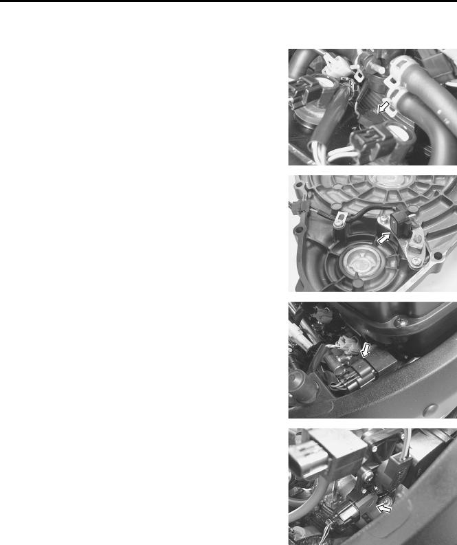
ECT SENSOR INSPECTION
The engine coolant temperature sensor is installed at the cylinder head. ( 4-49)
ECT SENSOR REMOVAL AND INSTALLATION
•Remove the ECT sensor. ( 7-7)
•Install the ECT sensor in the reverse order of removal.
ECT sensor: 18 N·m (1.8 kgf-m, 13.0 lb-ft)
IAT SENSOR INSPECTION
The intake air temperature sensor is installed to the air cleaner box. ( 4-53)
IAT SENSOR REMOVAL AND INSTALLATION
• Lift and support the fuel tank. ( 5-3)
• Remove the IAT sensor from the air cleaner box.
• Install the IAT sensor in the reverse order of removal.
AP SENSOR INSPECTION |
L |
E |
|
The AP sensor is located under the front seat. ( 4-57) |
|
AP SENSOR REMOVAL AND INSTALLATIONP |
|
• Remove the AP sensor from the frame. |
|
A |
|
• Install the AP sensor in the reverse order ofMremoval. |
|
S |
|
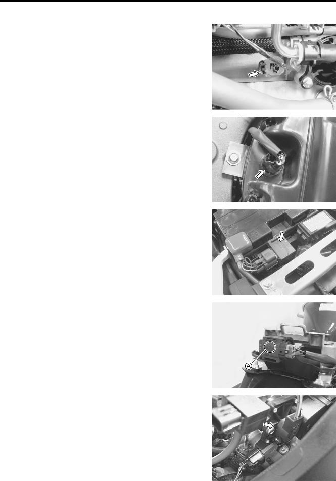
TO SENSOR INSPECTION
TO SENSOR REMOVAL AND INSTALLATION
The tip-over sensor is located at the rear of seat tail rail. ( 4-63)
•Remove the TO sensor.
•Install the TO sensor in the reverse order of removal.
NOTE:
When installing the TO sensor, the arrow mark A must be pointed upward.
STP SENSOR INSPECTION
STP SENSOR REMOVAL AND INSTALLATION
The secondary throttle position sensor is installed at the right side of the No. 4 throttle body.
•Remove the aircleaner box and lift up the throttle body. ( 5-14)
•Remove the STP sensor. ( 5-17)
•Install the STP sensor in the reverse order of removal.

FI SYSTEM DIAGNOSIS 4-107
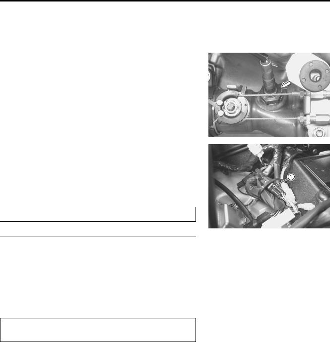
• Remove the right under cowling. ( 8-5)
• Lift and support the fuel tank. ( 5-3)
• Disconnect the coupler 1 and remove the HO2 sensor.
|
|
|
|
|
E |
Do not remove the HO2 sensor while it is hot. |
|
|
|||
|
|
|
L |
||
|
|
|
|||
|
P |
|
|
||
|
|
|
|
||
|
|
|
|
||
Be careful not to expose it to excessive shock. |
|
|
|
||
Do not use an impact wrench while removing or |
|
|
|||
installing the HO2 sensor. |
M |
|
|
|
|
|
|
|
|
||
Be careful not to twist or damage the sensor lead |
|
|
|||
wires. |
A |
|
|
|
|
S |
|
|
|
|
|
|
|
|
|
|
• Installation is in the reverse order of removal.
Do not apply oil or other materials to the sensor air hole.
• Tighten the sensor unit to the specified torque.
HO2 sensor: 48 N·m (4.8 kgf-m, 34.5 lb-ft)
• Route the HO2 sensor lead wire properly.( 10-20)