

9 - 110 3.3/3.8L ENGINE |
|
Ä |
|
Fig. 27 Hydraulic Roller Tappet Assembly
CLEANING AND ASSEMBLY
(1)Clean all tappet parts in a solvent that will remove all varnish and carbon.
(2)Replace tappets that are unfit for further service with new assemblies.
(3)If plunger shows signs of scoring or wear, valve is pitted, or valve seat on end of plunger indicates any condition that would prevent valve from seating, install a new tappet assembly.
(4)Assemble tappets (Fig. 27).
INSTALLATION
(1)Lubricate tappets.
(2)Install tappets in their original positions.
(3)With roller tappets, install aligning yokes with (Fig. 26).
(4)Install yoke retainer and torque screws to 12 Nzm (105 in. lbs.) (Fig. 26).
(5)Install cylinder heads. Refer to cylinder head installation of this section for procedure.
(6)Start and operate engine. Warm up to normal operating temperature.
CAUTION: To prevent damage to valve mechanism, engine must not be run above fast idle until all hydraulic tappets have filled with oil and have become quiet.
VALVE TIMING
(1)Remove front valve cover and all 6 spark plugs.
(2)Rotate engine until the #2 piston is at TDC of the compression stroke.
(3)Install a degree wheel on the crankshaft pulley.
(4)With proper adaptor, install a dial into #2 spark plug hole. Using the indicator find TDC on the compression stroke.
(5)Position the degree wheel to zero.
(6)Remove dial indicator from spark plug hole.
(7)Place a 5.08mm (.200 inch) spacer between the valve stem tip of #2 intake valve and rocker arm pad. Allow tappet to bleed down to give a solid tappet effect.
(8)Install a dial indicator so plunger contacts the #2 intake valve spring retainer as nearly perpendicular as possible. Zero the indicator.
(9) Rotate the engine clockwise until the intake valve has lifted .254mm (0.010 inch).
CAUTION: Do not turn crankshaft any further clockwise as intake valve might bottom and result in serious damage.
(10) Degree wheel should read 3 degrees BTDC to 4 degrees ATDC.
TIMING CHAIN COVER, OIL SEAL AND CHAIN
COVER
REMOVAL
(1)Disconnect battery.
(2)Drain cooling system. Refer to Cooling System Group 7 for procedure.
(3)Support engine and remove right engine mount.
(4)Raise vehicle on hoist. Drain engine oil.
(5)Remove oil pan and oil pump pick-up. It may necessary to remove transmission inspection cover.
(6)Remove right wheel and inner splash shield.
(7)Remove drive belt. Refer to Cooling System Group 7 for procedure.
(8)Remove A/C compressor and set aside.
(9)Remove A/C compressor mounting bracket.
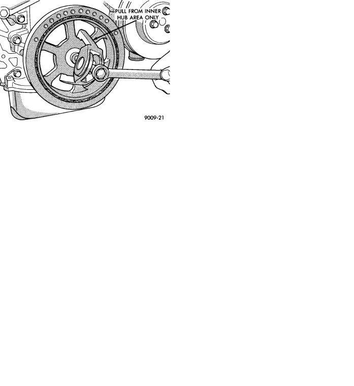
(10)Remove crankshaft pulley (Fig. 1).
(11)Remove idler pulley from engine bracket.
(12)Remove engine bracket (Fig. 2).
(13)Remove cam sensor from chain case cover (Fig. 3).
(14)Remove chain case cover (Fig. 3).
Fig. 1 Removing Crankshaft Pulley
Ä |
|
3.3/3.8L ENGINE 9 - 111 |
|
Fig. 2. Engine Bracket
MEASURING TIMING CHAIN FOR STRETCH
(1)Place a scale next to timing chain so that any movement of chain may be measured.
(2)Place a torque wrench and socket on camshaft sprocket attaching bolt and apply torque in direction of crankshaft rotation to take up slack; 41 Nzm (30 ft. lb.) with cylinder head installed or 20 Nzm (15 ft. lb.) with cylinder heads removed. With a torque applied to the camshaft sprocket bolt, crankshaft should not be permitted to move. It may be necessary to block crankshaft to prevent rotation.
(3)Holding a scale even, with dimension reading as shown (Fig. 4), along edge of chain links. Apply torque in the reverse direction to 41 Nzm (30 ft. lbs.) with cylinder heads installed, or 20 Nzm (15 ft. lbs.) with cylinder heads removed. Check amount of chain movement (Fig. 4).
(4)Install a new timing chain, if its movement exceeds 3.175mm (1/8 inch) (Fig. 4).
(5)If chain is not satisfactory, remove camshaft sprocket attaching bolt, and remove timing chain with camshaft sprocket.
(6)Using a suitable puller remove the crankshaft pulley. Be careful not to damage the crankshaft surface.
(7)Position a new crankshaft sprocket on the shaft, install sprocket with suitable tool and mallet. Be sure sprocket is seated into position.
(8)Rotate crankshaft sprocket so the timing mark is to the 12 o'clock position.
(9)Place timing chain around camshaft sprocket and place the timing mark to the 6 o'clock position.
(10)Place timing chain around crankshaft sprocket and install camshaft sprocket into position.
(11)Using straight edge to check alignment of timing marks (Fig. 5).
(12)Install camshaft bolt and washer. Tighten to 47 Nzm (35 ft. lbs.).
Fig. 3 Timing Chain Case Cover
Fig. 4 Measuring Timing Chain Wear and Stretch
(13)Rotate crankshaft 2 revolutions. Timing marks should line up. If timing marks do not line up remove cam sprocket and realign.
(14)Check camshaft endplay. With new thrust plate specification is .0127 to .304 mm (.005 to .012 inches.). Old thrust plate specification is .31 mm (.012 inch.) maximum. If not within these limits install new thrust plate.
(15)Install timing chain snubber. Tighten retaining screws to 12 Nzm (105 in lbs.). These bolts are
20mm long for this model year, they should not be interchanged with previous year engines.
INSTALLATION
(1)Be sure mating surfaces of chain case cover and cylinder block are clean and free from burrs. Crankshaft oil seal must be removed to insure correct oil pump engagement.
(2)Use a new cover gasket, O-rings. (Fig. 6).
(3)Rotate crankshaft so that the oil pump drive flats are vertical.

9 - 112 3.3/3.8L ENGINE
Fig. 5 Alignment of Timing Marks
(4)Position oil pump inner rotor so the mating flats are in the same position as the crankshaft drive flats (Fig. 6).
(5)Install cover onto crankshaft. Make sure the oil pump is engaged on the crankshaft correctly or severe damage may result.
(6)Install chain case cover screws and torque to 27 Nzm (20 ft. lbs.).
(7)Install crankshaft oil seal (Fig. 7).
(8)Install crankshaft pulley (Fig. 8).
Fig. 6 Timing Chain Case Cover Gaskets and
O-Rings
(9)Install engine bracket (Fig. 2) torque screws to 54 Nzm (40 ft. lbs.).
(10)Install idler pulley on engine bracket.
(11)Install cam sensor Refer to Ignition System Group 8D for installation procedure.
Ä
Fig. 7 Install Crankshaft Oil Seal
Fig. 8 Installing Crankshaft Pulley
(12)Install A/C compressor mounting bracket.
(13)Install A/C compressor.
(14)Install drive belt Refer to Cooling System Group 7 for installation procedure.
(15)Install inner splash shield and wheel.
(16)Install oil pump pick-up and oil pan and transmission inspection cover if removed.
(17)Install engine mount.
(18)Fill crankcase with oil to proper level.
(19)Fill cooling system Refer to Cooling System Group 7 for procedure.
(3)Connect battery.
TIMING CHAIN COVER EXTERNAL OIL SEAL
REMOVAL
(1)Raise vehicle on hoist. Remove right wheel and inner splash shield.
(2)Remove drive belt. (Refer to Cooling System Group 7) for procedure.
(3)Remove crankshaft pulley (Fig. 1).