

Ä |
|
3.0L ENGINE 9 - 81 |
|
(2)Install head on locating dowels.
(3)Install 10mm allen hex head bolts with wash-
ers.
(4)Tighten bolts in the order shown in (Fig. 16). When tightening the cylinder head bolts, tighten gradually, working in two or three steps and finally tighten to specified torque of 108 Nzm (80 ft. lbs.).
VALVE SPRINGS
VALVE AND VALVE SPRINGS
Fig. 19 Valve Inspection
(3) Check for even contact (at face center) with valve seat, Point C.
(4) Check margin. Replace valve if margin is out of specification (Fig. 20).
(5) Measure valve stem to guide clearance.
(6) Measure Valve spring free length and squareness (Fig. 21). Refer to (Fig. 20) for specifications.
Fig. 17 Remove Valves
Fig. 18 Remove Valve Stem Seals
(1)With suitable valve spring compressor, remove spring retainer locks, retainer, valve spring, spring seat and valve (Fig. 17).
(2)Remove valve stem seals with suitable tool (Fig. 18). Do not reuse valve stem seals.
VALVES
(1)Check valve stem tip for pitting or depression at point A (Fig. 19).
(2)Check for wear and ridge wear at Point B.
Fig. 20 Valve Specification
VALVE SEAT INSPECTION
Inspect the valve seat with Prussian blue to determine where the valve contacts the seat. To do this, coat valve seat LIGHTLY with Prussian blue then set valve in place. Rotate the valve with light pressure. If the blue is transferred to the center of valve face, contact is satisfactory. If the blue is transferred to top edge of the valve face, lower valve seat with a
9 - 82 3.0L ENGINE |
|
Ä |
|
Fig. 21 Valve Spring
Fig. 22 Valve Seat Reconditioning
15 degrees stone. If the blue is transferred to the bottom edge of valve face raise valve seat with a 65 degree stone.
(1)Install valve spring seat.
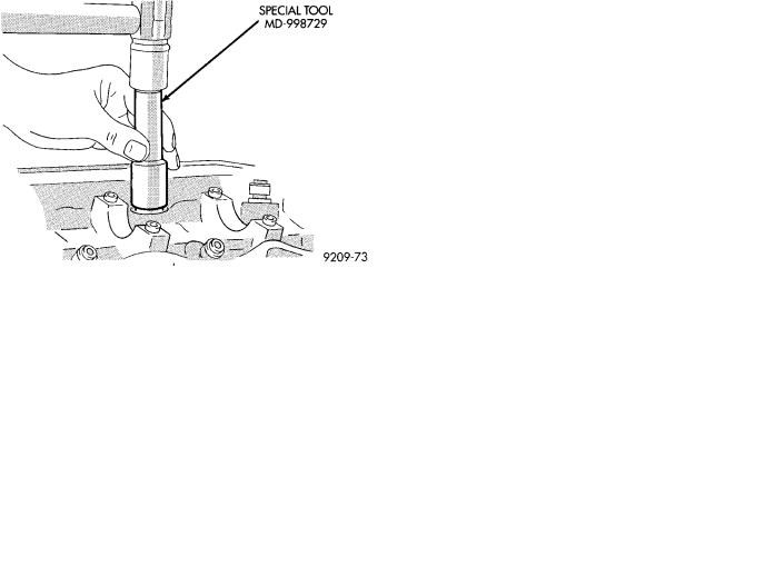
(2)Using suitable tool install seal by tapping lightly until seal is in place. (Fig. 23).
(3)Install valve spring with the enamelled ends facing the rocker arms (Fig. 24).
CAUTION: During reassembly, compressing the valve spring more than necessary to install valve
Fig. 23 Install Valve Stem Seals
Fig. 24 Installed Valve Spring Position
spring retainer locks can cause the retainer to be forced against the stem seal and damaging it.
Ä |
|
3.0L ENGINE 9 - 83 |
|
PISTON AND CONNECTING ROD ASSEMBLY
SERVICE
Fig. 1 Pistons, Connecting Rods
Fig. 2 Mark Pistons
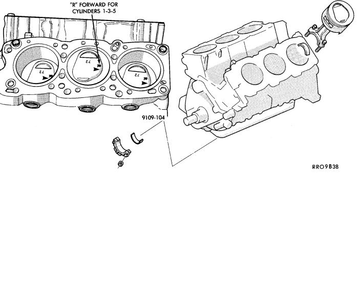
(1)Mark Identify Pistons. The pistons are not interchangeable from bank to bank (Fig. 2).
(2)Mark connecting rod and cap with cylinder number (Fig. 3).
(3)Remove piston rings (Fig. 4).
Fig. 3 Mark Matching Parts
FITTING PISTONS
Measure approximately 2mm (.080 inch) above the bottom of the piston skirt and across the thrust face. (Fig. 6), See Boring Cylinder in Cylinder Block.
FITTING PISTON RINGS
CYLINDER BORE INSPECTION
(1)Measure the cylinder bore at three levels in directions A and B (Fig. 5). Top measurement should be 12mm (.50 inch) down and bottom measurement should be 10mm (.38 inch) up.
(2)Standard bore dimension: 91.1mm (3.587 inch)
(3)Maximum out-of-round or taper: 0.02mm (.0008
inch)
(1)Wipe cylinder bore clean. Insert ring and push down with piston to ensure it is square in bore. The ring gap measurement must be made with the ring positioning at least 16mm (0.63 inch) from bottom of cylinder bore. Check gap with feeler gauge (Fig. 7). Refer to (Fig. 8) for specification.
(2)Check piston ring to groove clearance; Refer to Piston Ring Specification Chart (Fig. 8).
9 - 84 3.0L ENGINE |
|
Ä |
|
Fig. 4 Removing Piston Rings
Fig. 5 Checking Cylinder Bore Size
Fig. 6 Piston Clearance and Wear
Fig. 7 Check Gap on Piston Rings
Fig. 8 Piston Ring Specification Chart
Fig. 9 Piston Ring Clearance
PISTON RINGSÐINSTALLATION
(1) The No. 1 and No. 2 piston rings have a different cross section. Install rings with manufacturers mark and size mark facing up, to the top of the piston (Fig. 10).