


Ä
OIL PAN
A formed steel oil pan provides lower engine protection as well as serving as the engine oil reservoir (Fig. 1). Pan side flanges to block are sealed with gaskets. The oil pickup tube for some 2.2L engines have a circular strainer and cover. The 2.5L engine pickup is also unsupported and the lower end has a box type strainer (Fig. 4).
PRESSURE LUBRICATION
Oil drawn up through the pickup tube is pressurized by the pump and routed through the full flow filter to the main oil gallery running the length of the cylinder block (Fig. 2). Modified oil pickup, pump and check valve provide increased oil flow to the main oil gallery.
MAIN/ROD BEARINGS
A diagonal hole in each bulkhead feeds oil to each main bearing. Drilled passages within the crankshaft route oil from main bearing journals to crankpin journals.
ACCESSORY SHAFT
Two separate holes supply the accessory shaft.
BALANCE SHAFTS
The engine balance shafts are lubricated by an additional hole that interconnects a passage in one leg of the balance shaft carrier to route oil down to the carrier oil gallery. This gallery directly supplies the balance shafts front bearing and internal machined passages in the shafts routes oil from front to rear shaft bearing journals.
TURBOCHARGER (WHERE EQUIPPED)
If turbocharger equipped, pressurized oil from the main gallery to sending unit hex fitting is piped from the fitting to the turbocharger bearing housing. From the housing a hose and tube connection to machined hole in the block provides drainback.
CAMSHAFT/HYDRAULIC LIFTERS
A vertical hole at the number five bulkhead routes pressurized oil through a restrictor up past a cylinder head bolt to an oil gallery running the length of the cylinder head. Hydraulic adjusters are supplied directly from this gallery while diagonal holes supply oil to the camshaft journals. The camshaft journals are partially slotted to allow a predetermined amount of pressurized oil to pass into the bearing cap cavities with small holes directed to spray lubricate the camshaft lobes.
SPLASH LUBRICATION
Oil returning to the pan from pressurized components supplies lubrication to the valve stems. Cylinder bores and wrist pins are splash lubricated from directed holes in the connecting rods.
2.2/2.5L ENGINES 9 - 59
OIL PAN
REMOVAL
(1)Drain engine oil and remove oil pan.
(2)Clean oil pan and all gasket surfaces.
OIL PAN RAIL TO BLOCK SEALING
For all engines side gaskets (Fig. 1) are employed for rail sealing.
Fig. 3 Sealing, Front and Rear End Seals
INSTALLATION
(1)Apply Mopar Silicone Rubber Adhesive Sealant or equivalent at the front seal retainer parting line (Fig. 3).
(2)Install the oil pan side gaskets to the block. Use heavy grease or Mopar Silicone Rubber Adhesive Sealant or equivalent to hold in place.
(3)Apply Mopar Silicone Rubber Adhesive Sealant or equivalant to ends of new oil pan end seals at junction or cylinder block pan rail gasket (Fig. 3).
(4)Install pan and tighten screws to (12) M8 to 23 Nzm (200 in. lbs.) and 1 M6 to 12 Nzm (105 in. lbs.).
OIL PUMP SERVICE
OIL PICKUP
(1)Remove screw on pump cover holding oil pick-up tube to oil pump (Fig. 4).
(2)Remove oil pick-up tube. When reinstalling make sure to use a new O-ring on pickup tube.
OIL PUMP
REMOVAL
(1) Remove two (2) screws holding oil pump to cylinder block assembly (Fig. 5).
INSTALLATION
(1)Apply Mopar Gasket to pump body-to-block interface (machined surface).
(2)Lubricate oil pump rotor & shaft and drive gear.
9 - 60 2.2/2.5L ENGINES |
|
Ä |
|
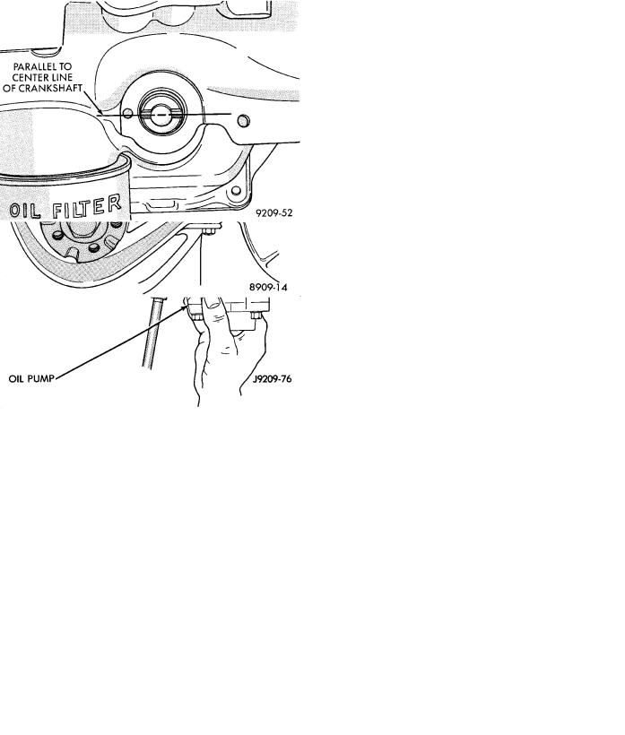
ter line of crankshaft when intermediate shaft and crankshaft are properly timed (Fig. 7).
(5) Install pump full depth and rotate back and forth slightly to ensure proper positioning and alignment through full surface contact of pump and block machined interface surfaces (Fig. 5).
CAUTION: Pump must be held in fully seated position (described above) while installing screws.
(6) Tighten screws to 23 Nzm (200 in. lbs.).
Fig. 4 Oil Pick-Up
Fig. 5 Oil Pump Assembly
(3)Turn crankshaft and intermediate shaft until markings on sprockets are in line (arrows Fig. 6).
(4)Slot in oil pump shaft must be parallel to cen-
Fig. 6 Crankshaft and Intermediate Shaft Timing
Fig. 7 Oil Pump Shaft Alignment
INSPECTION
(1)Check rotor end clearance with feeler gauge as shown in (Fig. 8).
(2)Limits:
²0.03mm (.001 inch) minimum.
²0.09mm (.0035 inch) maximum.
Ä |
|
2.2/2.5L ENGINES 9 - 61 |
|
Fig. 8 Checking Rotor End Clearance
(3)Thickness: 23.96mm (.9435 inch) minimum. Outer Diameter: 62.7mm (2.469 inch) minimum (Fig. 9).
(4)Install wiht large chamfered edge in pump body (Fig. 9).
Fig. 9 Measuring Outer Rotor
Clearance: 0.20mm (.008 inch) maximum (Fig. 10). Clearance: 0.35mm (.014 inch) maximum (Fig. 11). Clearance: 0.076mm (.003 inch) maximum (Fig. 12). Oil pressure relief valve spring: Free length: 49.5mm (1.95 inch). Load: 89 N at 34mm. Load: (20
lbs. at 1.34 inch) (Fig. 13).
Thickness: 23.96mm (.9435 inch) Minimum (Fig. 14).
Fig. 10 Clearance Between Rotors
Fig. 11 Outer Rotor Clearance
Fig. 12 Oil Pump Cover