

Ä
CRANKSHAFT SERVICE
CRANKSHAFT MAIN BEARINGS
Bearing caps are not interchangeable and should be marked at removal to insure correct assembly. Upper and lower bearing halves are NOT interchangeable. Lower main bearing halves of 1, 2, 4 and 5 are interchangeable. Upper main bearing halves of 1, 2, 4 and 5 are interchangeable (Fig. 7).
CRANKSHAFT MAIN JOURNALS
The crankshaft journals should be checked for excessive wear, taper and scoring. Limits of taper or out-of-round on ny crankshaft journals should be held to .025mm (.001 inch). Journal grinding should not exceed .305mm (.012 inch) under the standard journal diameter. Do NOT grind thrust faces of Number 3 main bearing. Do NOT nick crank pin or bearing fillets. After grinding, remove rough edges from crankshaft oil holes and clean out all passages.
CAUTION: With the nodular cast iron crankshafts used it is important that the final paper or cloth polish after any journal regrind be in the same direction as normal rotation in the engine.
Upper and lower Number 3 bearing halves are flanged to carry the crankshaft thrust loads and are NOT interchangeable with any other bearing halves in the engine (Fig. 7). All bearing cap bolts removed during service procedures are to be cleaned and oiled before installation. Bearing shells are available in standard and the following undersized: 0.025mm (.001 inch), .051mm (.002 inch), .076mm (.003 inch),
.254mm (.010 inch), and .305mm (.012 inch). Never install an undersized bearing that will reduce clearance below specifications.
Fig. 7 Main Bearing Identification
2.2/2.5L ENGINES 9 - 43
MAIN BEARING SERVICE−CRANKSHAFT NOT REMOVED
REMOVAL
(1)Remove oil pan and identify bearing caps before removal.
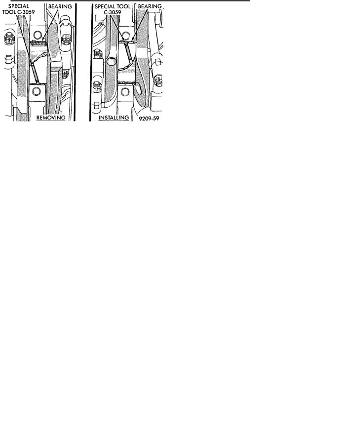
(2)Remove bearing caps one at a time. Remove upper half of bearing by inserting Special Main Bearing Tool C-3059 (Fig.8) into the oil hole of crankshaft.
(3)Slowly rotate crankshaft clockwise, forcing out upper half of bearing shell.
Fig. 8 Removing and Installing Upper Main Bearing
With Special Tool C-3059
INSTALLATION
Only one main bearing should be selectively fitted while all other main bearing caps are properly tightened.
When installing a new upper bearing shell, slightly chamfer the sharp edges from the plain side.
(1)Start bearing in place, and insert Main Bearing Tool C-3059 into oil hole of crankshaft (Fig. 8).
(2)Slowly rotate crankshaft counter-clockwise sliding the bearing into position. Remove Special Main Bearing Tool C-3059.
CHECKING CRANKSHAFT END PLAY
(1)Mount a dial indicator to front of engine, locating probe on nose of crankshaft (Fig. 9).
(2)Move crankshaft all the way to the rear of its travel.
(3)Zero the dial indicator.
(4)Move crankshaft all the way to the front and read the dial indicator. Refer to (Fig. 10) for specifications.
OPTIONAL CRANKSHAFT END PLAY CHECK
(1) Move crankshaft all the way to the rear of its travel using a lever inserted between a main bearing
9 - 44 2.2/2.5L ENGINES |
|
Ä |
|
Fig. 9 Checking Crankshaft End Play
cap and a crankshaft cheek, using care not to damage any bearing surface. Do not loosen main bearing cap.
(2) Use a feeler gauge between number three thrust bearing and machined crankshaft surface to determine end play.
Fig. 10 Crankshaft Specifications
CRANKSHAFT BEARING CLEARANCE
(1) Refer to Measuring Main, Connecting Rod Bearing Clearance in Standard Service Procedures. Refer to (Fig. 10) for specifications.
CAUTION: Do not rotate crankshaft or the Plastigage may be smeared.
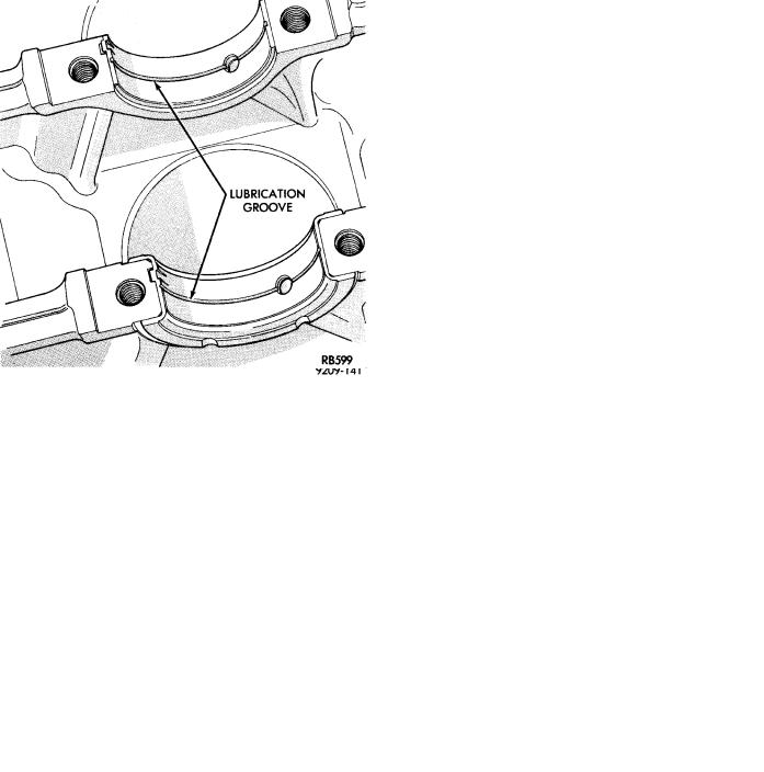
(2) Install the main bearing shells with the lubrication groove in the cylinder block (Fig. 12). The 1, 2, 4 and 5 main bearings are full groove to provide
Fig. 11 Checking Crankshaft Oil Clearance with Plastigage
Fig. 12 Installing Main Bearing Upper Shell
full time oiling to the connecting rod. Only the number 3 is half-groove.
(3)Make certain oil holes in block line up with oil hole in bearings and bearing tabs seat in the block tab slots.
(4)Oil the bearing and journals and install crank-
shaft.
(5)Install main bearing cap No.1 on timing belt
end.
(6)Install main bearing cap No. 5 on transmission
end.
Since the main bearing bolts are torqued using a new procedure they should be examined BEFORE reuse. If the threads are necked down the bolts should be replaced (Fig. 15).