

Ä |
|
3.0L ENGINE 9 - 77 |
|
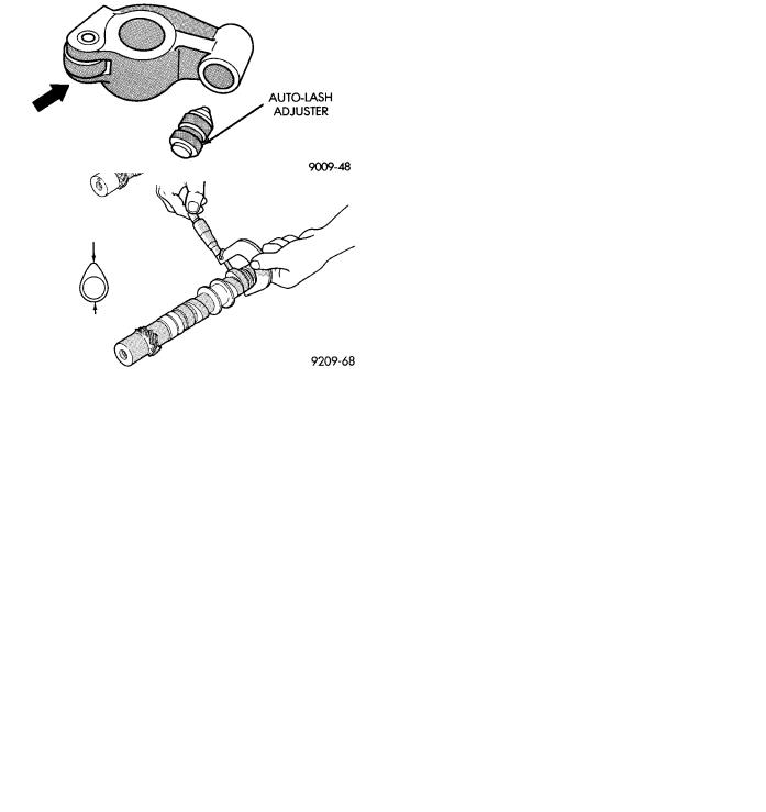
Fig. 3 Auto Lash Adjuster Check
Fig. 4 Auto Lash Adjuster Retainers
CAMSHAFT SERVICE
SEE AUTO LASH ADJUSTER FUNCTION CHECK BEFORE DISASSEMBLY
REMOVAL
(1)Install auto lash adjuster retainers. (Fig. 4).
(2)Remove distributor extension (Fig. 1).
(3)When removing camshaft bearing caps do not remove the bolts from the bearing caps. Remove the rocker arm, rocker shafts and bearing cap as an assembly.
CAMSHAFT INSPECTION
(1) Inspect camshaft bearing journals for damage and binding (Fig. 5). If journals are binding, also check the cylinder head for damage (Fig. 1). Also check cylinder head oil holes for clogging.
Fig. 5 Check Camshafts
(2)Front cylinder head camshaft check the tooth surface of the distributor drive gear teeth of the camshaft and replace if abnormal wear is evident (Fig. 5).
(3)Check the cam surface for abnormal wear and damage and replace if defective. Also measure the cam height (Fig. 5) and replace if out of limit, standard value is 41.25 mm (1.624 inch), wear limit is 40.75 mm (1.604 inch).
CAMSHAFT INSTALL
Lubricate camshaft journals and cams with engine oil and istall camshaft on cylinder head.
Fig. 6 Inspect Rocker Arms
ROCKER ARMS
(1) Check rocker arms for wear or damage (Fig. 6). Replace as necessary. Also see Auto Lash Adjuster.
ROCKER ARM SHAFTS
The rocker arm shaft is hollow and is used as a lubrication oil duct. The rocker arm shaft on the inlet

9 - 78 3.0L ENGINE |
|
Ä |
|
Fig. 7 Rocker Arm Shaft Identification
side has a 3mm diameter oil passage hole from the cylinder head. The exhaust side does not have this oil passage (Fig. 7).
(1)Check the rocker arm mounting portion of the shafts for wear or damage. Replace if heavily damaged or worn.
(2)Check oil holes for clogging with small wire, clean as required (Fig. 7).
REASSEMBLE
Fig. 8 Camshaft Bearing Caps Position
(1)Align the camshaft bearing caps with arrows (depending on cylinder bank) directed as shown in (Fig. 8) and in numerical order.
Identify number one bearing cap number one and number four caps are similar (Fig. 9).
(2)Install rocker shafts so that bearing cap number one with end notches positioned as shown in Figure 9 that the machined portion of the rocker shaft is facing down.
(3)Insert attaching bolts to retain assembly.
Fig. 9 Number One Camshaft Bearing Cap
ASSEMBLE ROCKER ASSEMBLY
Install the rocker arms, bearing caps and springs.
Springs are the same and can be used at all locations on the rocker arm shafts (Figs. 8 and 10). Insert bolts in number four bearing cap to retain assembly.
INSTALL ROCKER ARM SHAFT ASSEMBLY
(1)Apply Mopar Silicone Rubber Adhesive Sealant at bearing cap ends as shown in (Fig. 8).
(2)Install the rocker arm shaft assembly making sure that the arrow mark on the bearing cap and the arrow mark on the cylinder head are in the same direction. (Fig. 8).
The direction of arrow marks on the front and rear assemblies are opposite to each other.
(3)Tighten bearing cap bolts in the following order to 10 Nzm (85 in. lbs.). First #3, then #2, #1 and #4.
(4)Repeat step 3 increasing the torque to 20 Nzm (180 in. lbs.).
(5)Install distributor drive adaptor assembly (Fig.
11).
CAMSHAFT OIL SEAL SERVICEÐENGINE OUT OF VEHICLE
(1)Apply light coat of engine oil to the camshaft oil seal lip.
(2)Install the oil seal using camshaft oil seal installer tool MD998713 (Fig. 12).
CAMSHAFT END SEAL (PLUG) SERVICEÐIN VEHICLE SERVICE
(1)Remove air cleaner assembly from engine.
(2)Use a small punch and a hammer, carefully remove cam plug from cylinder head.
(3)Clean the area of the cylinder head where the new cam plug will be installed.
(4)Apply a light coating of Mopar Silicone Rubber Adhesive Sealant to the outer diameter of the NEW cam plug.
(5)Using a suitable installing tool and a hammer,