

9 - 102 3.3/3.8L ENGINE
(2)Loosen the right engine mount insulator yoke screw and 2 turns on yoke nut, then loosen the front engine mount bracket to front crossmember screws and nuts.
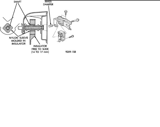
Left engine mount insulator is sleeved over shaft and long support bolt to provide lateral movement adjustment with engine weight removed or not.
(3)Pry the engine right or left as required to achieve the proper drive shaft assembly length. See Drive Shaft in Suspension Group 2 for driveshaft identification and related assembly length measuring.
(4)Tighten right engine mount insulator yoke nut to 102 Nzm (75 ft. lbs.). Then tighten front engine mount screws and nuts to 54 Nzm (40 ft. lbs.) and center left engine mount insulator.
(5)Recheck drive shaft length.
Fig. 4 Left Insulator Movement
ENGINE ASSEMBLY
REMOVAL
(1)Disconnect battery.
(2)Mark hood position at hinges and remove hood.
(3)Drain cooling system. Refer to Cooling System, Group 7 for procedure.
(4)Disconnect all electrical connections.
(5)Remove coolant hoses from radiator and engine.
(6)Remove radiator and fan assembly.
(7)See Fuel System, Group 14, to release fuel pressure. Disconnect fuel lines and accelerator cable.
(8)Remove air cleaner assembly.
(9)Hoist vehicle and drain engine oil.
(10)Remove air conditioning compressor mounting bolts and set compressor aside.
(11)Disconnect exhaust pipe at manifold.
(12)Remove transmission inspection cover and mark flex plate to torque converter position. For disassembly procedure for the all wheel drive vehicle refer to Group 21 Transaxle.
Ä
(13)Remove screws holding torque converter to flex plate and attach C-clamp on bottom of converter housing to prevent torque converter from counting out.
(14)Remove power steering pump mounting bolts and set pump aside.
(15)Remove two lower transmission to block screws.
(16)Remove starter.
(17)Lower vehicles and disconnect vacuum lines and ground strap.
(18)Install transmission holding fixture.
(19)Attach engine lifting hoist and support engine.
(20)Remove upper transmission case to block bolts.
(21)See Engine Mounting in (Fig. 3) and separate mount/insulators as follows:
(a)Mark RIGHT insulator on right rails supports. Remove insulator to rails screws.
(b)Remove FRONT engine mount through bolt and nut.
(c)Remove LEFT insulator through bolt from inside wheelhouse or insulator bracket to transmission screws.
(22)Remove engine.
INSTALLATION
(1)Attach hoist and lower engine into engine compartment.
(2)Align engine mounts and install but do not tighten until all mounting bolts have been installed. Tighten bolts to torque specified in (Fig. 3).
(3)Install transmission case to cylinder block, tighten bolts to 102 Nzm (75 ft. lbs.) torque.
(4)Remove engine hoist and transmission holding fixture.
(5)Remove C-clamp from torque converter housing. Align flex plate to torque converter and install mounting screws. Tighten to 75 Nzm (55 ft. lbs.) torque. Refer to Group 21 transaxle for the all wheel drive installation procedure.
(6)Install transmission inspection cover.
(7)Connect exhaust system at manifold.
(8)Install starter.
(9)Install power steering pump and air conditioning compressor. For belt installation see Accessory Belt Drive in Cooling System Group 7.
(10)Lower vehicle and connect all vacuum lines.
(11)Connect all electrical connections including ground strap.
(12)Connect fuel lines and accelerator cable.
(13)Install radiator and fan assembly. Reconnect fan motor electrical lead. Reinstall radiator hoses. Fill cooling system. See Cooling System Group 7 for filling procedure.
(14)Fill engine crankcase with proper oil to correct
level.