

Ä |
|
3.0L ENGINE 9 - 69 |
|
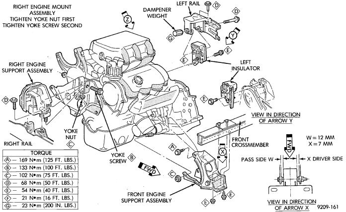
Fig. 2 Engine Mounting
shaped and provides the same spring tension as longer springs. Valve spring retainers, lock and seals are conventional.
INTAKE MANIFOLD: The aluminum alloy manifold is a cross type with long runners to improve inertia. The runners, attaching below at the cylinder head, also attach above and support an air plenum. The air plenum chamber absorbs air pulsations created during the suction phase of each cylinder.
EXHAUST MANIFOLDS: Both manifolds are a log style made of ductile cast iron. Exhuast gasses, collected from the front cylinder bank, leave the front manifold through an end outlet and are fed through an upper crossover tube to the rear manifold. The collected exhaust from both manifolds are combined, and exit to the exhaust pipe through an articulated joint.
ENGINE LUBRICATION: System is a full flow filtration, pressure feed type. The oil pump is mounted in the chaincase cover. The pump inner rotor is driven by the crankshaft. The engine oil pan contains a baffle plate to control oil level fluctuation during engine operation.
ENGINE MOUNTS
REMOVAL AND INSTALLATION
RIGHT SIDE MOUNT
(1)Remove the right engine mount insulator vertical fasteners from frame rail.
(2)Remove the load on the engine motor mounts by carefully supporting the engine and transmission assembly with a floor jack.
(3)Remove the thru bolt from the insulator assembly. Remove insulator.
(4)Reverse removal procedure for installation. Refer to (Fig. 2) for bolt tightening specifications.
(5)Engine mount adjustment, Refer to Engine Mount Insulator Adjustment of this section.
FRONT MOUNT
(1)Support the engine and transmission assembly with a floor jack so it will not rotate.
(2)Remove the thru bolt from the insulator and front crossmember mounting bracket.
(3)Remove the front engine mount bracket to front crossmember screws and nuts. Remove the insulator assembly.
(4)Reverse removal procedure for installation. Refer to (Fig. 2) for bolt tightening specifications.