


9 - 22 2.2/2.5L ENGINES |
|
Ä |
|
CYLINDER HEAD AND VALVE ASSEMBLY SERVICE
Fig. 1 Cylinder Head and Valve Assembly Service
Ä |
|
2.2/2.5L ENGINES 9 - 23 |
|
Fig. 2 Cylinder Head Cover and Curtain
CYLINDER HEAD COVER AND CURTAIN
A curtain aiding air/oil separation is installed on the cylinder head below the cylinder head cover (Figs. 1 and 2).
REMOVAL
(1)Remove the cylinder head cover bolts (Fig. 2).
(2)Remove cylinder head cover and curtain from cylinder head. Do not misplace the rubber bumpers on curtain.
CLEANING
Before installation, clean cylinder head and cover mating surfaces. Make certain the rails are flat.
CURTAIN INSTALLATION
Install curtain manifold side first with cutouts over cam towers and contacting cylinder head floor, then press opposite distributor side into position below cylinder head rail.
Fig. 3 Cylinder Head Valve Cover Rail Sealing
Curtain is retained in position with rubber bumpers (Fig. 1).
COVER SEALING AND INSTALLATION
Before installation, clean cylinder head and cover mating surfaces. Make certain rails are flat.
(1)Install new end seals on valve cover.
(2)Apply form-in-place Mopar Silicone Rubber Adhesive Sealant or equivalent gasket material to cylinder head cover rail (Fig. 3). Refer to procedure detailed in form-in-place gasket section of Standard Service Procedures, in this Group.
CAUTION: Do not allow oil or solvents to contact the timing belt as they can deteriorate the rubber and cause tooth skipping.
(3) Install curtain, cover and end seal assembly to head and tighten to 12 Nzm (105 in. lbs.) torque.
CYLINDER HEAD COMPONENTS−IN-VEHICLE SERVICE
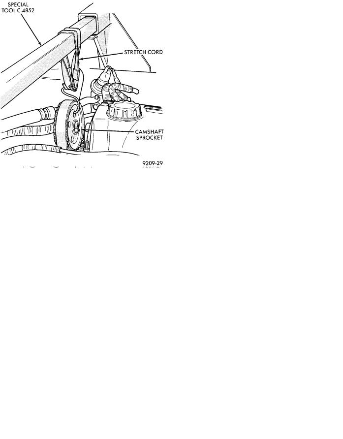
Removal and installation of cylinder head or camshaft require separation of camshaft timing sprocket from camshaft. To maintain camshaft, intermediate shaft, and crankshaft timing during service procedures, the timing belt is left indexed on the sprocket while the assembly is suspended under light tension (Fig. 4).
When removing the sprocket from the camshaft, you must maintain adequate tension on the sprocket and belt assembly to prevent the belt from disengaging with the intermediate or crankshaft timing sprocket. Refer to Timing System and Seals for re-
Fig. 4 Suspending Camshaft Sprocket
9 - 24 2.2/2.5L ENGINES |
|
Ä |
|
Fig. 5 Engine Sprocket Timing
moval and installation of camshaft sprocket procedure and to Camshaft Service for removal and installation of camshaft procedures.
CAUTION: Failure to maintain adequate tension on camshaft, intermediate, and crankshaft sprocket belt can result in lost engine timing. If timing is lost, refer to Timing System and Seals and (Fig. 4).
CAMSHAFT SERVICE
Refer to TIMING SYSTEM AND SEALS for cam-
shaft timing belt and sprocket removal and installation, and CYLINDER HEAD In Vehicle Service.
REMOVAL
(1)Remove the cylinder head cover and curtain.
(2)Mark rocker arms for reinstallation in the same position (Fig. 6).
(3)Loosen camshaft bearing cap screws several revolutions (Fig. 7).
(4)Jar camshaft at rear of cam to loosen (break free) the bearing caps. Use a soft faced mallet.
CAUTION: Care should be exercised not to cock the camshaft during removal. Cocking of the camshaft could cause damage to the cam or bearing thrust surfaces.
(5) Remove screws and caps such that cam does not cock.
INSPECTION
Check bearing cap and oil feed holes for blockage. Inspect bearing cap and cylinder head journals for wear and/or oversize, Refer to CYLINDER HEAD,
Inspect and Specifications.
Fig. 7 Camshaft Cap Removal Sequence
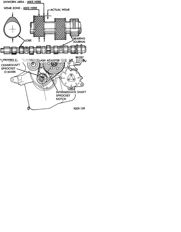
Fig. 8 Camshaft
Chamshaft bearing journals and lobe wear. Lobe wear should not exceed .25mm (.010 inch). To mea-
Fig. 6 Rocker Arm and Lash Adjuster

Ä |
|
2.2/2.5L ENGINES 9 - 25 |
|
Fig. 9 Camshaft End Play
sure cam lobe wear (Fig. 8), measure lobe diameter in two places at the largest diameter (over the nose). Take first reading with micrometer in unworn area at the edge of the lobe. Take second reading in the worn area where rocker arm contacts the lobe. Subtract second reading from the first. The difference is the cam lobe wear.
CAMSHAFT END PLAY
(1)Oil camshaft journals and install camshaft without cam followers. Tighten screws to specified torque.
(2)Using a suitable tool, move camshaft as far rearward as it will go.
(3)Zero dial indicator (Fig. 9).
(4)Move camshaft as far forward as it will go.
(5)End play travel: 0.13 - 0.33mm (0.005 - 0.013 inch.).
(6)Remove bearing caps and camshaft.
INSTALLATION
(1)Install cam followers in correct order as removed.
(2)Align camshaft bearing caps in proper sequence with Cap No. 1 at timing belt end and Cap No. 5 at transmission end. Arrows on Caps No. 1, 2, 3, 4 must point toward timing belt to prevent cap breaking (Fig. 11).
(3)Apply Mopar Gasket Maker to No. 1 and No. 5 bearing cap (Fig. 10).
(4)Caps must be installed before camshaft seals are installed.
LASH ADJUSTER (TAPPET) NOISE
A tappet-like noise may be produced from several items. Refer to Lash Adjuster and Tappet Noise - Diagnosis in Standard Service Procedures, this Group.
Fig. 10 Cam Tower Cap Sealing
Fig. 11 Camshaft Bearing Caps Installation
VALVE COMPONENTS REPLACE−CYLINDER HEAD NOT REMOVED
ROCKER ARM AND HYDRAULIC LASH ADJUSTER
REMOVAL
(1)Remove valve cover.
(2)For each rocker arm, rotate cam until base circle is in contact with rocker arm. Depress valve spring using Special Tool C-4682 (Fig. 12) and slide rocker arm out. Keep rocker arms in order for reassembly.
(3)Remove hydraulic lash adjuster.
INSTALLATION
(1)Install hydraulic lash adjuster making sure that adjusters are at least partially full of oil. This is indicated by little or no plunger travel when the lash adjuster is depressed.
(2)Rotate cam until base circle is in contact position with rocker arm. Depress valve spring with Special Tool C-4682 (Fig. 12) and slide rocker arm in place. Keep rockers in order. It is possible for the