

9 - 52 2.2/2.5L ENGINES
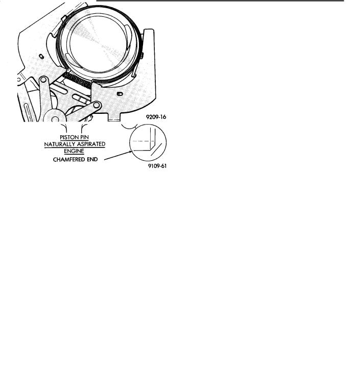
PISTON PINS
DISASSEMBLY
Turborcharged engine piston-pin-connecting rod assemblies should not be disassembled unless a malfunction is present or a damaged assembly component is to be replaced.
WARNING: APPROVED SAFETY GLASSES MUST BE WORN DURING PISTON LOCK RING REMOVAL OR INSTALLATION TO PREVENT POSSIBLE INJURY FROM FLYING PARTS.
Fig. 11 Engine Piston Pins−Turbo and N.A.
(1)Carefully, remove piston pin lock rings from piston, using a small screwdriver in removal notch (Fig. 10).
(2)Discard used lock ring.
(3)Following lock ring removal, attempt to slide pin out of piston. If pin does not slide out freely by hand;
²Check for burr on outer edge of lock ring groove. If one is present, carefully scrape burr away with a knife or other hand tool, being careful not to damage lock ring retaining groove.
(4)Slide out piston pin to complete disassembly.
(5)Inspect components, discard damaged or excessively worn parts refer to specifications (Fig. 12). If a piston is replaced, a new pin should be used.
PISTON PINS
REASSEMBLY
(1) Two different lock rings are used for turbocharged engine applications. Consult the Service
Ä
Note, provided with the lock ring service package, to select the correct lock rings from the package for your application.
(2)Carefully, install one NEW lock ring with gap towards piston top in lock ring groove. Do not reinstall used lock rings.
(3)Position connecting rod and slide in lightly oil piston pinch
(4)Install second NEW lock ring with gap towards piston top in lock ring groove, use small screwdriver if needed.
CAUTION: BOTH lock rings must be FULLY SEATED in lock ring grooves or engine failure will occur.
(5) Check piston pin end play pin movement between lock rings in assembly.
Fig. 12 Piston Pin Specifications
Fig. 13 Piston Rings−Removing and Installing
PISTON RING−REMOVAL
(1)ID mark on face of upper and intermediate piston rings must point toward piston crown.
(2)Using a suitable ring expander, remove upper and intermediate piston rings (Fig. 13).
(3)Remove the upper oil ring side rail, lower oil ring side rail and then oil ring expander from piston.
(4)Clean ring grooves of any carbon deposits.
Ä
Fig. 14 Piston Ring Gap
Fig. 15 Piston Ring Groove Clearance
FITTING RINGS
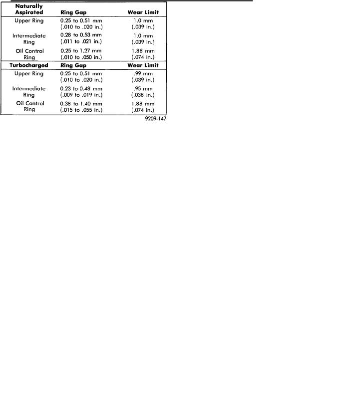
(1)Wipe cylinder bore clean. Insert ring and push down with piston to ensure it is square in bore. The ring gap measurement must be made with the ring positioning at least 12mm (.50 inch) from bottom of cylinder bore. Check gap with feeler gauge (Fig. 14). Refer to specifications (Fig. 16, 17 and 18).
(2)Check piston ring to groove clearance: (Fig. 15). Refer to specification (Fig. 17).
PISTON RINGS−INSTALLATION
(1) The No. 1 and No. 2 piston rings have a different cross section. Install rings with manufacturers I.D. mark facing up, to the top of the piston (Fig. 13).
CAUTION: Install piston rings in the following order:
(a)Oil ring expander.
(b)Upper oil ring side rail.
(c)Lower oil ring side rail.
(d)No. 2 Intermediate piston ring.
(e)No. 1 Upper piston ring.
2.2/2.5L ENGINES 9 - 53
Fig. 16 Piston Ring Specifications−Turbo III
Fig. 17 Piston Ring Groove Specifications
Fig. 18 Piston Ring Gap Specifications
(2) Install the side rail by placing one end between the piston ring groove and the expander. Hold end firmly and press down the portion to be installed until side rail is in position. Do not use a piston ring expander. (Fig. 19).
9 - 54 2.2/2.5L ENGINES |
|
Ä |
|
(3)Install upper side rail first and then the lower side rail.
(4)Install No. 2 piston ring and then No. 1 piston ring (Fig. 8).
Fig. 19 Installing Side Rail
(5)Position piston ring end gaps as shown in (Fig.
20).
(6)Position oil ring expander gap at least 45° from the side rail gaps but not on the piston pin center or on the thrust direction. Staggering ring gap is important for oil control.
Fig. 20 Piston Ring End Gap Position
PISTON AND CONNECTING ROD ASSEMBLY INSTALLATION
(1)Before installing pistons and connecting rod assemblies into the bore, be sure that compression ring gaps are staggered so that neither is in line with oil ring rail gap.
(2)Before installing the ring compressor, make sure the oil ring expander ends are butted and the rail gaps located as shown in (Fig. 20).
(3)Immerse the piston head and rings in clean engine oil, slide the ring compressor, over the piston
Fig. 21 Installing Piston
and tighten with the special wrench (Fig. 21). Be sure position of rings does not change during this operaiton.
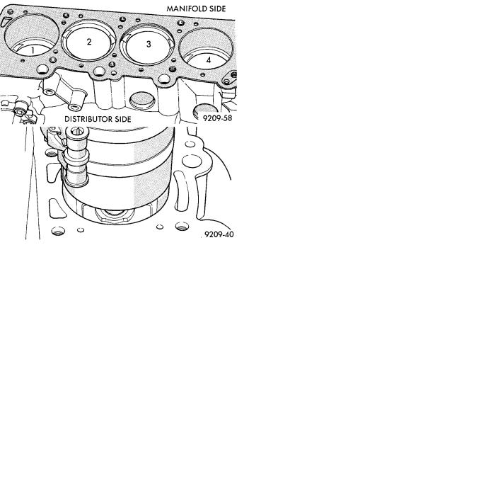
Fig. 22 Piston Markings
(4)The valve cut should be toward the manifold side of the engine (Fig. 22 ).
(5)Install connecting rod bolt protectors on rod bolts (Fig. 4).
(6)Rotate crankshaft so that the connecting rod journal is on the center of the cylinder bore. Insert rod and piston into cylinder bore and guide rod over the crankshaft journal.
(7)Tap the piston down in cylinder bore, using a hammer handle. At the same time, guide connecting rod into position on connecting rod journal.
(8)Intall rod caps. Install nuts on cleaned and oiled rod bolts and tighten nuts to 54 Nzm (40 ft. lb.) Plus 1/4 turn.