

Ä |
|
3.0L ENGINE 9 - 85 |
|
Fig. 10 Piston Ring Installation
CAUTION: Install piston rings in the following order:
(a)Oil ring expander.
(b)Upper oil ring side rail.
(c)Lower oil ring side rail.
(d)No. 2 Intermediate piston ring.
(e)No. 1 Upper piston ring.
Fig. 11 Installing Side Rail
(2)Install the side rail by placing one end between the piston ring groove and the expander. Hold end firmly and press down the portion to be installed until side rail is in position. Do Not use a piston ring expander (Fig. 11).
(3)Install upper side rail first and then the lower side rail.
(4)Install No. 2 piston ring and then No. 1 piston ring (Fig. 12).
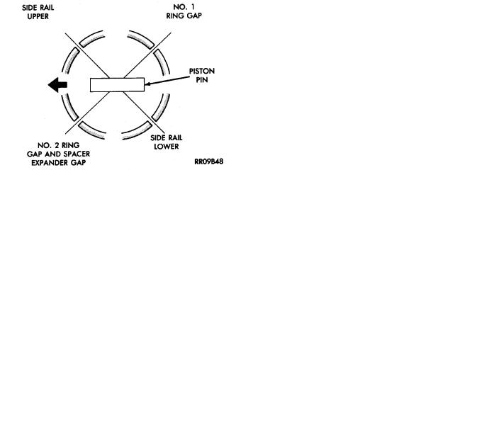
(5)Position piston ring end gaps as shown in (Fig.
13).
(6)Position oil ring expander gap at least 45° from the side rail gaps but not on the piston pin center or on the thrust direction.
Fig. 12 Installing Upper and Intermediate Rings
Fig. 13 Piston Ring End Gap Position
(7)Connecting rod front mark 72 must always face forward, toward timing belt end. (Fig. 14)
(8)Install the piston and connecting rod assembly into there respective bore from the cylinder block top.
CAUTION: Piston assemblies are not to be interchanged from bank to bank.
(9) Check alignment marks made during disassembly and that bearing position notches new or used are on the same side as shown in (Fig. 15).
CONNECTING ROD CLEARANCE
(1)Following procedures specified in the Standard Service Procedures Section for Measuring Main Bearing Clearance and Connecting Rod Bearing Clearance. (Fig. 16). Refer to (Fig. 18) for specifications.
(2)Tighten nuts to 52 Nzm (38 ft. lbs.).
9 - 86 3.0L ENGINE |
|
Ä |
|
Fig. 14 Identify Piston/Rod Assembly for Cylinder Installation
Fig. 15 Connecting Rod and Cap
(3) Remove connecting rod cap and measure Plastigage (Fig. 16).
CAUTION: Do not rotate crankshaft or the Plastigage may be smeared.
CONNECTING ROD SIDE CLEARANCE
Using a feeler gauge, check connecting rod side clearance (Fig. 17). Refer to (Fig. 18) for specification.
Fig. 16 Connecting Rod Checking Bearing
Clearance
Fig. 17 Checking Connecting Rod Side Clearance
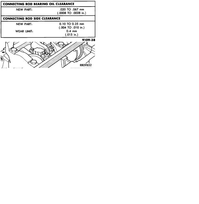
Fig. 18 Connecting Rod Clearance Specifications
Ä |
|
3.0L ENGINE 9 - 87 |
|
CRANKSHAFT AND CYLINDER BLOCK, ASSEMBLY
SERVICE
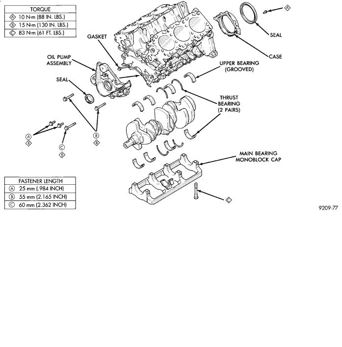
Fig. 1 Crankshaft and Cylinder Block
CRANKSHAFT SERVICE
The crankshaft is supported in four main bearings. All upper bearing shells in the crankcase have oil grooves. All lower bearing shells installed in the monoblock main bearing cap are plain. Crankshaft end play is controlled by thrust washers on the number three main bearing journal.
CRANKSHAFTÐREMOVAL
(1)Remove front mounted oil pump assembly and gasket (Figs. 1 and 2).
(2)Remove rear oil seal retainer and seal as assembly (Fig. 3).
(3)Release monoblock main bearing cap bolts evenly. Remove lower bearing shells and identify for reassembly.
(4)Lift out crankshaft and remove upper thrust washers from each side of number three main bearing in the crankcase (Fig. 1).
INSPECTION
Visually check the main and connecting rod bearing journals for wear, scuffs or scoring and replace if necessary.
Fig. 2 Oil Pump Assembly
CRANKSHAFT OIL CLEARANCE
MECHANICAL MEASUREMENT
Measure the journal outside diameter and the main bearing inside diameter (Figs. 4 and 5). If the clearance exceeds the specifications limit (Fig. 6). Replace the main bearing(s) and if necessary replace the crankshaft.
9 - 88 3.0L ENGINE |
|
Ä |
|
Fig. 3 Rear Seal Assembly
Fig. 4 Measure Crankshaft Journal O.D.
Fig. 5 Measure Main Bearing I.D.
PLASTIGAGE MEASUREMENT
(1)Remove oil from journal and bearing shell.
(2)Install crankshaft.
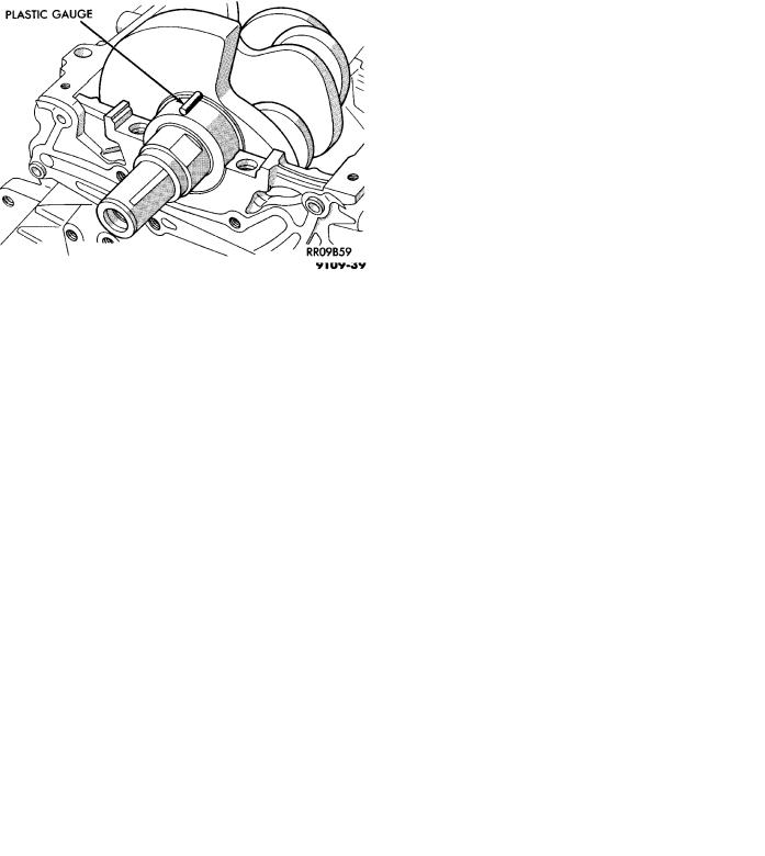
(3)Cut plastigage to same length as width of the bearing and place it in parallel with the journal axis. (Fig. 7).
Fig. 6 Crankshaft Clearance Specification
(4) Install the main bearing cap carefully and tighten the bolts to specified torque.
CAUTION: Do not rotate crankshaft or the plastigage will be smeared.
Fig. 7 Measure Oil Clearance with Plastigage
(5) Carefully remove the bearing cap and measure the width of the plastigage at the widest part using the scale on the plastigage package (Fig. 8). Refer to specification (Fig. 6) for proper clearances. Also see Measuring Main and Connecting Rod Bearing Clearance in Standard Service Procedures.
CRANKSHAFT BEARINGS
INSTALLATION
(1) Install upper main bearing shells making certain oil holes are in alignment, and bearing tabs seat in block tabs. All upper bearings have oil grooves. (Fig. 9).
THRUST BEARINGS. Crankshaft thrust bearings (washers) are installed at journal #3 separately from the radial bearings. Thrust bearings shown in