

9 - 34 2.2/2.5L ENGINES
CAMSHAFT AND CRANKSHAFT TIMING PROCEDURE
INSTALLATION
(1)Remove air cleaner fresh air duct.
(2)Remove ignition cable cover (Fig. 7).
(3)Remove valve covers and loosen rocker arm assemblies about 3 turns as shown in (Fig. 8).
CAUTION: Check lash adjuster for loose or missing retainers before continuing service procedure.
(4)Align and pin both intake and exhaust cam sprockets with 3/32 drills or pin punches (Fig. 9).
Accessory Shaft does not need to be timed.
(5)Remove spark plugs.
Fig. 7 Ignition Cable Cover
Fig. 8 Rocker Arm Shaft Assemblies
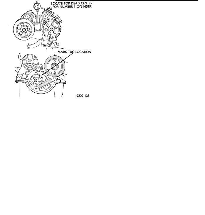
(6)Install a dial indicator in Number 1 spark plug hole (Fig. 10).
(7)Rotate crankshaft till number 1 piston is at Top Dead Center. Mark the engine block for TDC reference.
(8)Install timing belt and idler pulley in sequence shown in (Fig. 11).
(9)Remove dial indicator from cylinder head (Fig. 10). Remove drills or pins from camshaft sprockets (Fig. 11).
Ä
Fig. 9 Camshafts Pinned into Position
Fig. 10 Dial Indicator Located in Number 1 Cylinder
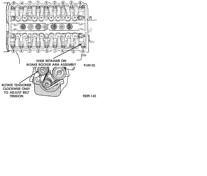
(10) Adjust tension to 445 N (110 lbs.) New belt or 311 N (70 lbs.) Used belt. Install belt tension gauge on timing belt (Fig. 12) adjust tensioner until specified tension is achieved.
CAUTION: Belt tension gauge must be installed between the belt teeth to get a accurate reading.
(11) Rotate crankshaft clockwise 2 full revolutions and check alignment of camshaft and crankshaft timing marks. Do not reverse rotate crankshaft or attempt to rotate engine using cam or accessory shaft attaching screw.
CAUTION: Do not allow oil or solvents to contact the timing belt as they can deteriorate the rubber and cause tooth skipping.
Ä |
|
2.2/2.5L ENGINES 9 - 35 |
|
Fig. 11 Camshafts and Crankshaft Timing Marks
(12)Recheck belt tension, adjust if necessary.
(13)Torque rocker arm shafts in sequence shown (Fig. 13) to 12 Nzm (105 in. lbs.) then to 24 Nzm (210 in. lbs.).
(14)Install valve covers, spark plugs, ignition cables and ignition cable cover.
(15)Install air cleaner fresh air duct.
(16)Raise vehicle. Install lower timing belt cover and accessory drive belt tensioner pulley. Refer to procedure in this section.
(17)Lower vehicle. Install right engine mount (Fig.
5).
(18)Install upper timing belt cover and PCV tube. Refer to procedure in this section.
(19)Install accessory drive belt. Refer to procedure in this section.
Fig. 12 Belt Tension Gauge Location
Fig. 13 Rocker Arm Shaft−Installation
SERVICING OIL SEALS
Refer to servicing oil seals in this group for procedures.
To service the intake cam seal (Turbo III) the right engine mount must be removed. Refer to engine mount removal of this Group.