

Ä
(15)Install hood.
(16)Connect battery.
(17)Start engine and run until operating temperature is reached.
(18)Adjust transmission or linkage if necessary.
ROCKER ARMS AND SHAFT ASSEMBLY
REMOVAL
(1)Remove upper intake manifold assembly. Refer to Intake and Exhaust Manifolds, Group 11.
(2)Disconnect spark plug wires by pulling on the boot straight out in line with plug.
(3)Disconnect closed ventilation system and evaporation control system from cylinder head cover.
(4)Remove cylinder head cover and gasket.
(5)Remove four rocker shaft bolts and retainers.
(6)Remove rocker arms and shaft assembly.
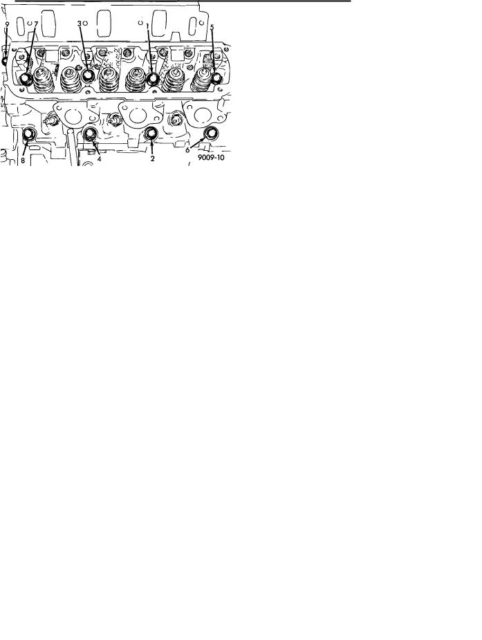
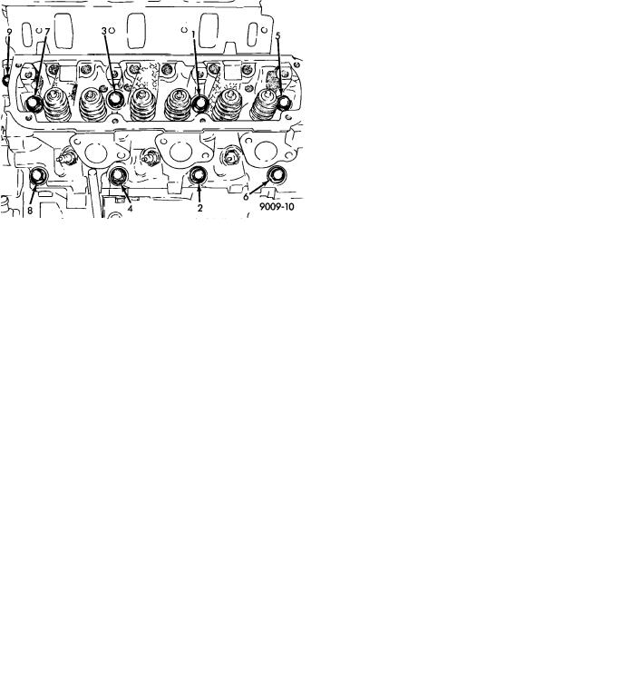
(7)If rocker arm assemblies are disassembled for cleaning or replacement. Assemble rocker arms in their original position. Refer to (Fig. 5) for rocker arm for positioning on the shaft.
Fig. 5 Rocker Arm Location Left Blank
INSTALLATION
(1)Install rocker arm and shaft assemblies with the stamped steel retainers in the four positions, tighten to 28 Nzm (250 in. lbs.) (Fig. 5).
WARNING: THE ROCKER ARM SHAFT SHOULD BE TORQUED DOWN SLOWLY, STARTING WITH THE CENTERMOST BOLTS. ALLOW 20 MINUTES TAPPET BLEED DOWN TIME AFTER INSTALLATION OF THE ROCKER SHAFTS BEFORE ENGINE OPERATION.
(2)Clean cylinder head cover gasket surface. Inspect cover for distortion and straighten if necessary.
(3)Clean head rail if necessary. Install a new gasket and tighten cylinder head cover fasteners to 12 Nzm (105 in. lbs.).
(4)Install closed crankcase ventilation system and evaporation control system.
3.3/3.8L ENGINE 9 - 103
(5)Install spark plug wires.
(6)Install upper intake manifold assembly. Refer to Exhaust Systems and Intake Manifolds Group 11.
CYLINDER HEADS
The alloy aluminum cylinder heads shown in (Fig. 6) are held in place by 9 bolts. The spark plugs are located in peak of the wedge between the valves.
Fig. 6 Cylinder Head Assembly
REMOVAL
(1)Drain cooling system refer to Cooling System Group 7 for procedure and disconnect negative battery cable.
Remove intake manifold, and throttle body. Refer to Group 11 Exhaust System and Intake Manifold.
(2)Disconnect coil wires, sending unit wire, heater hoses and by-pass hose.
(3)Remove closed ventilation system, evaporation control system and cylinder head covers.
(4)Remove exhaust manifolds.
(5)Remove rocker arm and shaft assemblies. Remove push rods and identify to insure installation in original locations.
(6)Remove the 9 head bolts from each cylinder head and remove cylinder heads (Fig. 7).
Fig. 7 Cylinder Head Bolts Location
9 - 104 3.3/3.8L ENGINE |
|
Ä |
|
INSPECTION
(1)Before cleaning, check for leaks, damage and cracks.
(2)Clean cylinder head and oil passages.
(3)Check cylinder head for flatness (Fig. 8).
(4)Inspect all surfaces with a straightedge if there is any reason to suspect leakage. If out of flatness exceeds .019mm (.00075 inch) times the span length in inches in any direction, either replace head or lightly machine the head surface. As an example, if a 12 inch span is 1mm (.004 inch) out of flat, allowable is 12 x .019mm (.00075 inch) equals .22mm (.009 in.). This amount of out of flat is acceptable.
*Maximum of 0.2 mm (.008 inch) for grinding is permitted.
CAUTION: This is a combined total dimension of stock removal from cylinder head and block top surface.
Fig. 8 Check Cylinder Head
INSTALLATION
(1)Clean all surfaces of cylinder block and cylinder heads.
(2)Install new gaskets on cylinder block (Fig. 9).
The Cylinder head bolts are torqued using the
torque yield method, they should be examined BEFORE reuse. If the threads are necked down, the bolts should be replaced (Fig. 10).
Necking can be checked by holding a scale or straight edge against the threads. If all the threads do not contact the scale the bolt should be replaced.
(3) Tighten the cylinder head bolts 1 thru 8 in the sequence shown in (Fig. 11). Using the 4 step torque turn method, tighten according to the following values:
²First-All to 61 Nzm (45 ft. lbs.)
²Second-All to 88 Nzm (65 ft. lbs.)
²Third-All (again) to 88 Nzm (65 ft. lbs.)
²Fourth + 1/4 Turn Do not use a torque wrench for this step
Fig. 9 Head Gasket Installation
Fig. 10 Checking Bolts for Stretching (Necking)
(4) Bolt torque after 1/4 turn should be over 122 Nzm (90 ft. lbs.). If not, replace the bolt.
Fig. 11 Cylinder Head Tightening Sequence
(5)Tighten head bolt number 9 (Fig. 11) to 33 Nzm (25 ft. lbs.) after head bolts 1 thru 8 have been tighten to specifications.
(6)Inspect push rods and replace worn or bent
rods.
(7)Install push rods, rocker arm and shaft assemblies with the stamped steel retainers in the four positions, tighten to 28 Nzm (250 in. lbs.) (Fig. 12).