

9 - 26 2.2/2.5L ENGINES |
|
Ä |
|
Fig. 12 Removing and Installing Valve Spring
valve spring retainer locks to become dislocated when depressing the valve spring. Check and make sure the locks are in their proper location.
(3) Install valve cover as previously outlined in this section.
VALVE SPRINGS AND VALVE STEM SEALS
REMOVAL
(1)Remove rocker arms as previously outlined in this section.
(2)Rotate crankshaft until piston is at TDC on compression.
(3)With air hose attached to adapter tool installed in spark plug hole, apply 90-120 psi air pressure.
(4)Using Special Tool C-4682 (Fig. 12) compress valve springs and remove valve locks.
(5)Remove valve spring.
(6)Remove valve stem seal by gently prying side- to-side with a screwdriver blade. Once dislodged from guide post, seal may be easily removed.
INSTALLATION
(1)Install valve seals (Fig. 13) as outlined in step
(2)of Valve Gear Reassembly - After Valve Service in this section.
(2)Using Special Tool C-4682 compress valve springs only enough to install locks. Correct alignment of tool is necessary to avoid nicking valve stems (air pressure required), piston at TDC.
(3)Install rocker arms as previously outlined in this section.
CYLINDER HEAD
REMOVAL
(1)Perform fuel system pressure release procedure before attempting any repairs. Refer to Fuel System Group 14.
(2)Disconnect negative battery cable. Drain cooling system. Refer to Cooling System, Group 7.
Fig. 13 Valve Stem Seals
(3)Remove air cleaner and disconnect all vacuum lines, electrical wiring and fuel lines from throttle body.
(4)Remove throttle linkage.
(5)Loosen power steering pump and remove belt.
(6)Remove power brake vacuum hose from intake manifold.
(7)Remove water hoses from water crossover.
(8)Raise vehicle and remove exhaust pipe from manifold.
(9)Remove power steering pump assembly and set aside.
(10)Disconnect coil wiring connector and coil wire from coil.
(11)Disconnect dipstick tube from thermostat housing and ROTATE bracket from stud. DO NOT bend the bracket.
(12)See Solid Mount Compressor Bracket in STANDARD SERVICE PROCEDURES, this Group.
(13)Remove cylinder head bolts.
INSPECT HEAD AND CAMSHAFT BEARING JOURNALS
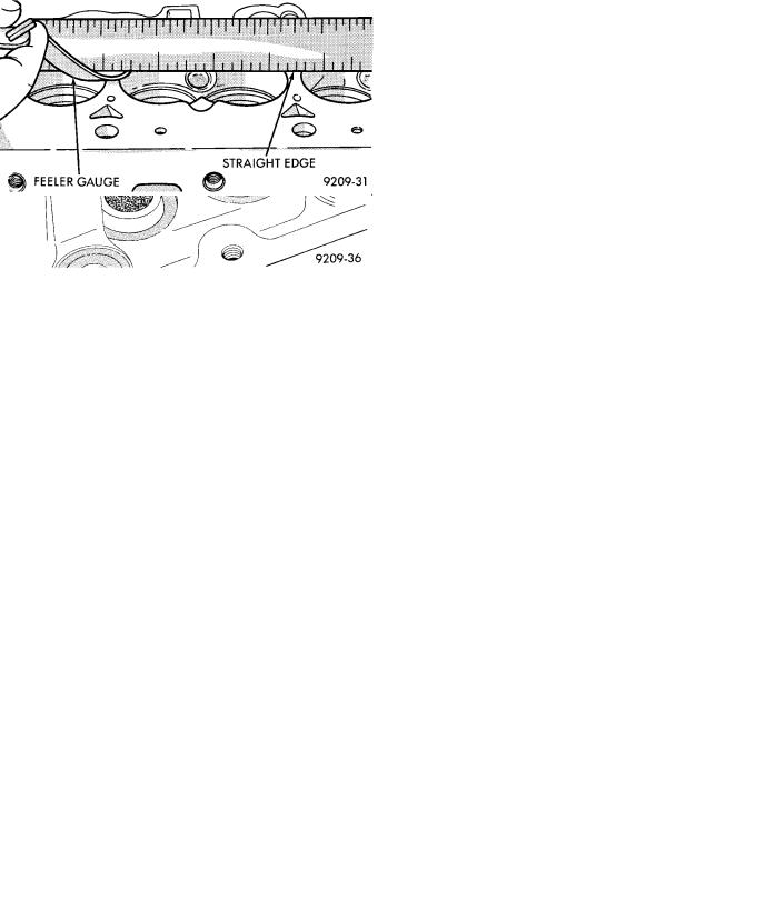
Fig. 14 Checking Cylinder Head Flatness
(1) Cylinder head must be flat within 0.1mm (.004 inch) (Fig. 14).
Ä |
|
2.2/2.5L ENGINES 9 - 27 |
|
(2) Inspect camshaft journals for scoring and journal caps for oversize markings. When servicing cylinder head or camshaft, it is necessary to be certain that oversized camshafts are used only in oversized heads. Identify oversize components as follows:
Cylinder Head: Top of bearing caps painted green and O/SJ stamped rearward of oil gallery plug on end of head.
Camshaft: Barrel of camshaft painted green and O/SJ stamped on end of shaft.
CLEANING
Remove all gasket material from cylinder head and block. Be careful not to gouge or scratch aluminum head sealing surface.
INSTALLING
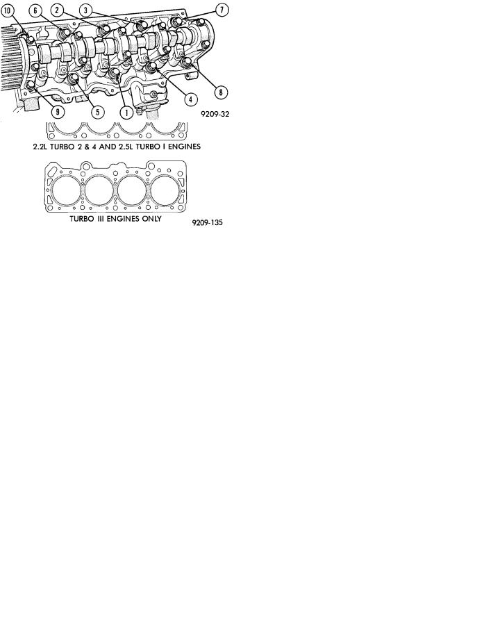
CAUTION: 2.5L turbo I engine head gasket is NOT the same as that used for prior years 2.2L turbo I engine (Fig. 15).
CAUTION: Head bolt diameter is 11mm. These bolts are identified with 11 on the head of the bolt. 10mm bolts will thread into the 11mm hole but will strip the cylinder block bolt hole.
Since the Cylinder head bolts are torqued using a new procedure they should be examined BEFORE reuse. If the threads are necked down the bolts should be replaced (Fig. 16).
Necking can be checked by holding a scale or straight edge against the threads. If all the threads do not contact the scale the bolt should be replaced.
Fig. 16 Checking Bolts for Stretching (Necking)
(1)Before installing the bolts the threads should be oiled with engine oil.
(2)Install both bolts in each cap finger tight, then alternately torque each bolt to assemble the cap properly.
(3)Tighten the cylinder head bolts in the sequence shown in (Fig. 17). Using the 4 step torque turn method, tighten according to the following values:
²First All to 61 Nzm (45 ft. lbs.)
²Second All to 88 Nzm (65 ft. lbs.)
²Third All (again) to 88 Nzm (65 ft. lbs.)
²Fourth + 1/4 Turn Do not torque wrench for this step.
Bolt torque after 1/4 turn should be over 90 ft. lbs. If not, replace the bolt.
(4)Rotate dipstick tube on bracket.
(5)Tighten bracket retaining nut to 23 Nzm (200 in.
lbs.)
Fig. 17 Cylinder Head Tightening Sequence
VALVE SERVICE−CYLINDER HEAD REMOVED
VALVES AND VALVE SPRINGS
REMOVAL
(1)With cylinder head removed, compress valve springs using Tool C-3422-B.
(2)Remove valve retaining locks, valve spring retainers, valve stem seals and valve springs.
(3)Before removing valves, remove any burrs from valve stem lock grooves to prevent damage to the valve guides. Identify valves to insure installation in original location.
Fig. 15 Cylinder Head Gaskets
9 - 28 2.2/2.5L ENGINES
VALVE INSPECTION
(1)Clean valves thoroughly and discard burned, warped and cracked valves.
(2)Measure valve stems for wear.
(3)If valve stems are worn more than 0.05 mm (.002 inch) replace valve.
VALVE GUIDES
(1)Remove carbon and varnish deposits from inside of valve guides with a reliable guide cleaner.
(2)Checking Valve Guide Wear:
²Insert valve with valve head positioned 10 mm (.400 inch) above cylinder head gasket surface.
²Move valve to and from the indicator (Fig. 17). The total dial indicator reading should not exceed the amount specified in (Fig. 18). Readings should be taken for lengthwise and crosswise (with respect to cylinder head) movement for each valve. Ream the guides for valves with oversize stems if dial indicator reading is excessive or if the stems are scuffed or scored.
Fig. 18 Checking Wear on Valve Guide−Typical
Fig. 19 Valve Guide Specification
(3) Service valves with oversize stems and oversize seals are available in 0.15mm, (.005 inch) 0.40mm, (.015 inch) and 0.80mm (.031 inch) oversize.
Oversize seals must be used with oversize valves.
Ä
Reamers sizes to accommodate the oversize valve stem are shown in (Fig. 18).
(4) Slowly turn reamer by hand and clean guide thoroughly before installing new valve. Do not attempt to ream the valve guides from standard directly to 0.80mm (.030 inch). Use step procedure of 0.15mm (.005 inch), 0.40mm (.015 inch) and 0.80mm (.030 inch) so the valve guides may be reamed true in relation to the valve seat. After reaming guides, the seat runout should be measured and resurfaced if necessary. See Refacing Valves and Valve Seats.
Replace cylinder head if guide does not clean up with 0.80 mm (.030 inch) oversize reamer, or if guide is loose in cylinder head.
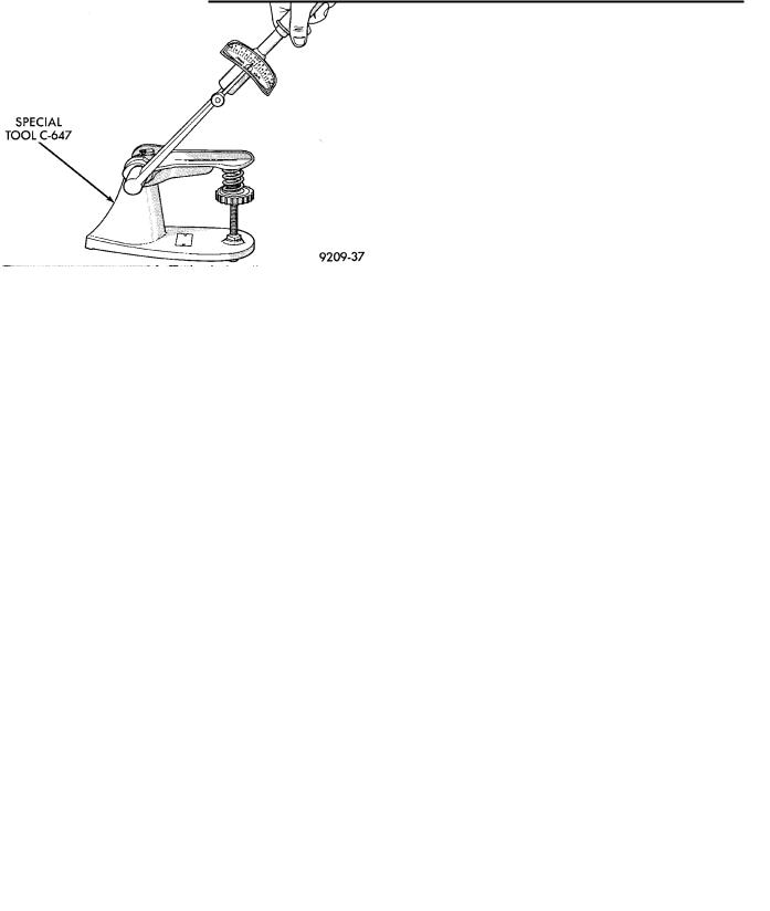
Fig. 20 Testing Valve Spring with Tool C-647
TESTING VALVE SPRINGS
(1)Whenever valves have been removed for inspection, reconditioning or replacement, valve springs should be tested. As an example, the compression length of the spring to be tested is 33.34mm (1-5/16 inches). Turn table of Tool C-647 until surface is in line with the 33.34mm (1-5/16 inch) mark on the threaded stud and the zero mark on the front. Place spring over stud on the table and lift compressing lever to set tone device (Fig.20). Pull on torque wrench until ping is heard. Take reading on torque wrench at this instant. Multiply this reading by two. This will give the spring load at test length. Fractional measurements are indicated on the table for finer adjustments. Refer to specifications to obtain specified height and allowable tensions. Discard the springs that do not meet specifications.
(2)Inspect each valve spring for squareness with a steel square and surface plate, test springs from both ends. If the spring is more than 1.5mm (1/16 inch) out of square, install a new spring.
REFACING VALVES AND VALVE SEATS
(1) The intake and exhaust valve seats and valve face have a 45 degree angle.
Ä |
|
2.2/2.5L ENGINES 9 - 29 |
|
Valve seats which are worn or burned can be reworked, provided that correct angle and seat width are maintained. Otherwise cylinder head must be replaced.
Fig. 21 Intake and Exhaust Valves
Fig. 22 Valve Dimensions
(2)Inspect the remaining margin after the valves are refaced (Fig. 23). Exhaust valves with less than 1.191mm (3/64 inch) margin and intake valves with less than .794mm (1/32 inch) margin should be discarded.
(3)When refacing valve seats, it is important that the correct size valve guide pilot be used for reseating stones. A true and complete surface must be obtained.
(4)Measure the concentricity of valve seat using a valve seat dial indicator. Total runout should not exceed .051mm (.002 inch) (total indicator reading).
(5)Inspect the valve seat with Prussian blue to determine where the valve contacts the seat. To do this, coat valve seat LIGHTLY with Prussian blue then set valve in place. Rotate the valve with light pressure. If the blue is transferred to the center of valve face, contact is satisfactory. If the blue is transferred to top edge of the valve face, lower valve seat with a 15 degrees stone. If the blue is transferred to the bottom edge of valve face raise valve seat with a 65 degrees stone.
²Intake valve seat diameter 40.45mm (1.593 inch)
²Exhaust valve seat diameter 34.84mm (1.371 inch)
Fig. 23 Refacing Intake and Exhaust Valves
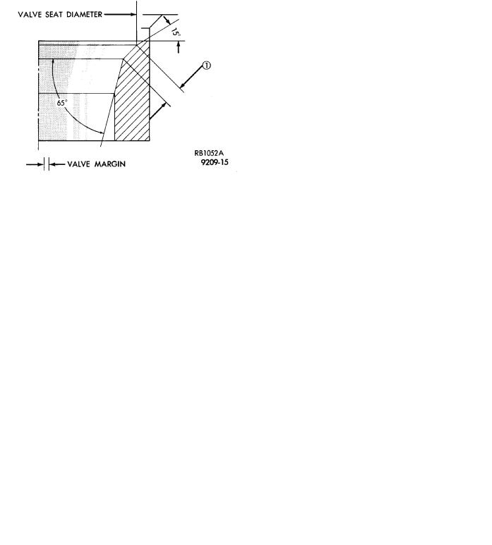
(6)When seat is properly positioned the width of intake seats should be 1.75 to 2.25mm (0.69 to .088 inch). The width of the exhaust seats should be 1.50 to 2.00mm (.059 to .078 inch) (Fig. 24 Dimension 1).
(7)Check valve tip to valve spring seat dimensions after grinding to seats or faces. Grind valve tip to give 49.76 to 51.04mm (1.960 to 2.009 inch) over valve spring seat when installed in the head (Fig. 25). The valve tip diameter should be no less than 7.0mm (0.275 inch), if necessary, the tip chamfer should be reground to prevent seal damage when the valve is installed.
Fig. 24 Refacing Valve Seats
(8) Check the valve spring installed height after refacing the valve and seat (Fig. 26).