

Ä |
|
3.3/3.8L ENGINE 9 - 105 |
|
(8) Place new cylinder head cover gaskets in position and install cylinder head covers. Tighten to 12 Nzm (105 in. lbs.).
are in place. Refer to Group 11 Exhaust System and Intake Manifold to complete Intake Manifold Assembly.
(5)Install exhaust manifolds and tighten bolts to 27 Nzm (20 ft. lb.) and nuts to 20 Nzm (15 ft. lbs.).
(6)Adjust spark plugs to specification in Electrical Section, Group 8, and install the plugs.
Fig. 12 Rocker Arm Shaft Retainers
INTAKE MANIFOLD SEALING
The intake manifold gasket is a one-piece stamped steel gasket with a sealer applied from the manufacturer. This gasket has end seals incorporated with it.
WARNING: INTAKE MANIFOLD GASKET IS MADE OF VERY THIN METAL AND MAY CAUSE PERSONAL INJURY, HANDLE WITH CARE.
(1)Clean all surfaces of cylinder block and cylinder heads.
(2)Place a drop (about 1/4 in. diameter) of Mopar Silicone Rubber Adhesive Sealant or equivalent, onto each of the four manifold to cylinder head gasket corners (Fig. 13).
Fig. 13 Intake Manifold Gasket Sealing
(3)Carefully install the intake manifold gasket (Fig. 14). Torque end seal retainer screws to 12 Nzm (105 in. lbs.).
(4)Install intake manifold and (8) bolts and torque to 1 Nzm (10 in. lbs.). Then retorque bolts to 22 Nzm (200 in. lbs.) in sequence shown in (Fig. 15). Then retorque again to 22 Nzm (200 in. lbs.). After intake manifold is in place, inspect to make sure seals
Fig. 14 Intake Manifold Gasket Retainers
Fig. 15 Intake Manifold Removal and Installation
VALVE SERVICE
VALVES AND VALVE SPRINGS
The valves are arranged in line in the cylinder heads and inclined 18 degrees. The rocker shaft support are cast integral with the heads.
REMOVAL
(1)With cylinder head removed, compress valve springs using Valve Spring Compressor Tool C-3422-B with adapter 6412 as shown in (Fig. 16).
(2)Remove valve retaining locks, valve spring retainers, valve stem seals and valve springs.
9 - 106 3.3/3.8L ENGINE |
|
Ä |
|
(3) Before removing valves, remove any burrs from valve stem lock grooves to prevent damage to the valve guides. Identify valves to insure installation in original location.
Fig. 16 Compress Valve Springs with Special Tool C-3422B with adapter 6412
VALVE INSPECTION
(1)Clean valves thoroughly and discard burned, warped and cracked valves.
(2)Measure valve stems for wear. Refer to specifications (Fig. 19).
Valve stems are chrome plated and should not be polished.
(3)Remove carbon and varnish deposits from inside of valve guides with a reliable guide cleaner.
(4)Measure valve stem guide clearance as follows:
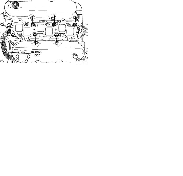
(a)Install valve into cylinder head so it is 14mm (.551 inch) off the valve seat. A small piece of hose may be used to hold valve in place.
(b)Attach dial indicator Tool C-3339 to cylinder head and set it at right angle of valve stem being measured (Fig. 17).
(c)Move valve to and from the indicator. Refer to specifications (Fig. 19).
Ream the guides for valves with oversized stems if
dial indicator reading is excessive or if the stems are scuffed or scored.
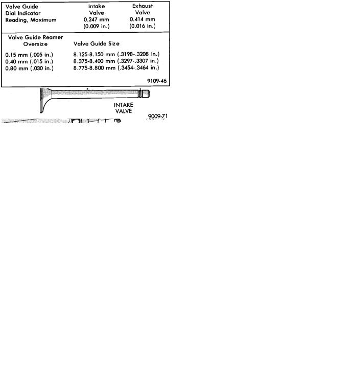
(5)Service valves with oversize stems and over size seals are available in 0.15mm (.005 inch), 0.40mm, (.015 inch) and 0.80mm (.030 inch) oversize.
Oversize seals must be used with oversize valves.
Reamers to accommodate the oversize valve stem are as follows:
(6)Slowly turn reamer by hand and clean guide thoroughly before installing new valve. Do not attempt to ream the valve guides from standard directly to 0.80mm (.030 inch) Use step procedure of 0.15mm (.005 inch), 0.40mm (.015 inch) and 0.80mm (.030 inch) so the valve guides may be reamed true in relation to the valve seat.
Fig. 17 Measuring Valve Guide Wear
Fig. 18 Intake and Exhaust Valves
Fig. 19 Valve Guide Specifications
After reaming guides, the seat runout should be measured and resurfaced if necessary. See Refacing Valves and Valve Seats.
VALVE GUIDES
Replace cylinder head if guide does not clean up with 0.80mm (.030 inch) oversize reamer, or if guide is loose in cylinder head.

Ä |
|
3.3/3.8L ENGINE 9 - 107 |
|
Fig. 20 Valve Dimensions
REFACING VALVES AND VALVE SEATS
The intake and exhaust valves have a 44-1/2 to 45 degree face angle. The valve seats have a 45 to 45-1/2 degree face angle. The valve face and valve seat angles are shown in (Fig. 21).
VALVES
(1) Inspect the remaining margin after the valves are refaced Refer to specifications (Fig. 20).
VALVE SEATS
CAUTION: Do not un-shroud cylinder head from around the valve during valve seat refacing (Fig. 22).
(1)When refacing valve seats, it is important that the correct size valve guide pilot be used for reseating stones. A true and complete surface must be obtained.
(2)Measure the concentricity of valve seat using dial indicator. Total runout should not exceed .051mm (.002 inch) total indicator reading.
Fig. 21 Valve Seats
(3) Inspect the valve seat with Prussian blue to determine where the valve contacts the seat. To do this, coat valve seat LIGHTLY with Prussian blue
Fig. 22 Refacing Valve Seats
then set valve in place. Rotate the valve with light pressure. If the blue is transferred to the center of valve face, contact is satisfactory. If the blue is transferred to top edge of valve face, lower valve seat with a 15 degree stone. If the blue is transferred to the bottom edge of valve face raise valve seat with a 65 degrees stone.
Valve seats which are worn or burned can be reworked, provided that correct angle and seat width are maintained. Otherwise cylinder head must be replaced.
(4)When seat is properly positioned the width of intake seats should be 1.75 to 2.25mm (0.69 to .088 inch) The width of the exhaust seats should be 1.50 to 2.00mm (.059 to .078 inch) (Fig. 21)
(5)Check the valve spring installed height after refacing the valve and seat (Fig. 24).
TESTING VALVE SPRINGS
Whenever valves have been removed for inspection, reconditioning or replacement, valve springs should be tested (Fig. 23). As an example: the compression length of the spring to be tested is 33.34mm (1-5/16 inches). Turn table of Tool C-647 until surface is in line with the 33.34mm (1-5/16 inch) mark on the threaded stud and the zero mark on the front. Place spring over stud on the table and lift compressing lever to set tone device. Pull on torque wrench until ping is heard. Take reading on torque wrench at this instant. Multiply this reading by two. This will give the spring load at test length. Fractional measurements are indicated on the table for finer adjustments. Refer to specifications to obtain specified height and allowable tensions. Discard the springs that do not meet specifications.
VALVE INSTALLATION
(1) Coat valve stems with clean engine oil and insert them in cylinder head.
9 - 108 3.3/3.8L ENGINE |
|
Ä |
|
Fig. 23 Testing Valve Spring with Tool C-647
Fig. 24 Checking Valve Installed Height
(2)If valves or seats are reground, check installed valve spring height (Fig. 24).
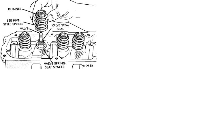
(3)Install new cup seals on all valve stems and over valve guides (Fig. 24). Install valve springs and valve retainers.
(4)Compress valve springs with Valve Spring Compressor Tool C-3422-B, with adapter 6412 install locks and release tool. If valves and/or seats are reground, measure the installed height of springs, make sure measurements is taken from top of spring seat to the bottom surface of spring retainer. If height is greater than 1-19/32 inches, (40.6mm), install a 1/32 inch (.794mm) spacer in head counterbore to bring spring height back to normal 1-17/32 to 1-19/32 inch (39.1 to 40.6mm).
REPLACE VALVE STEM SEALS OR VALVE SPRINGS, CYLINDER HEAD NOT REMOVED
(1)Perform fuel system pressure release procedure before attempting any repairs.
(2)Disconnect negative battery cable.
(3)Remove Air Cleaner Cover and hose assembly.
(4)Remove Intake Manifold; Refer to Intake/Exhaust Manifold 3.3/3.8L Engine Group 11 Exhaust System and Intake Manifolds of this manual for removal procedure.
Fig. 25 Installing Valve, Cup Seal, Spring and
Retainer
(5)Remove cylinder head covers and spark plugs.
(6)Remove connector wire from ignition coils.
(7)Using suitable socket and flex handle at crankshaft pulley retaining screw, turn engine so the number 1 piston is at Top Dead Center on the compression stroke.
(8)Remove rocker arms with rocker shaft and install a shaft. The rocker arms should not be disturbed and left on shaft.
(9)With air hose attached to spark plug adapter installed in number 1 spark plug hole, apply 90 to 100 psi air pressure (620.5 to 689 kPa). This is to hold valves into place while servicing components.
(10)Using Tool C-4682 or Equivalent compress valve spring and remove retainer valve locks and valve spring.
(11)The intake valve stem seals should be pushed firmly and squarely over the valve guide using the valve stem as a guide. Do Not Force seal against top of guide. When installing the valve retainer locks, compress the spring only enough to install the locks.
CAUTION: Do not pinch seal between retainer and top of valve guide.
(12)Follow the same procedure on the remaining 5 cylinders using the firing sequence 1-2-3-4-5-6. Make sure piston in cylinder is at TDC on the valve spring that is being covered.
(13)Remove spark plug adapter tool.
(14)Remove shaft and install rocker shaft assembly and tighten screws to 28 Nzm (250 in lbs.).
(15)Install rocker arm covers tighten screws to 14 Nzm (120 in. lbs.) and connector to ignition coils.
(16)Install Intake Manifold; Refer to Intake Manifold Installation 3.3/3.8L Engine, Group 11 Exhaust System and Intake Manifold.