


TIME FROM TRIP (SECONDS)
Fig. 1.39 Hydraulic transient response of 6-unit trip at Dinorwig.
site are the three-phase transformers. These may weigh up to 300 t. The shape of this load on its transport will determine the size of the access tunnels. The access tunnels can have a maximum gradient of 10%.
|
4.8 |
Availability of construction |
|
|||
|
labour |
|
|
|
||
|
The construction of a pumped storage scheme in |
|||||
i |
mountainous regions away from centres of population |
|||||
r |
provides |
problems |
of |
accommodation, |
education, |
|
; transport |
and |
training |
and |
local resistance to the use of |
||
|
travelling men on construction works. Many of the con- |
|||||
k |
struction |
activities can |
use |
local labour, possibly involv- |
||
i' |
ing retraining for the job, but this strategy also has |
|||||
; |
difficulties at the end of |
construction where |
the num |
|||
|
bers employed in the finished power station may be |
|||||
|
very small. This can act as a demotivating influence on |
|||||
|
the workforce as the project nears completion. |
|
||||
4.9 Environmental impact
The environmental impact of a pumped storage power station raises many issues:
1• Visual impact of station and electrical connections.
•Fisheries.
•Land taken for construction of reservoirs.
•Improvement of access routes and traffic movements.
•Import and export of construction materials.
•Restoration and repair of the natural landscape.
•Disposal of spoil from the construction works.
Gas turbines
•Hazard studies such as flooding by overtopping of either of the reservoirs.
At Dinorwig, the environmental problems were parti cularly difficult because of the location of the site in the Snowdonia National Park. The decision to place the majority of the works underground solved most of the problems and careful attention to detail has limited the long term visual impact of the station by strategies such as: removing construction roads, landscaping to hide access roads, and collection and storage of topsoil prior to construction followed by replacement and seeding after construction with locally-collected heather and grass species (see Fig 1.19).
5Gas turbines
5.1Introduction
Due to the nature and overall simplicity of gas turbine plant, great flexibility may be exercised when consider ing its suitability for siting at specific geographical locations. Compared to other forms of power gener ation plant, gas turbine stations require relatively small land areas and a limited number of site resources. The major considerations for siting gas turbine plant are the transportation of fuel to the site and the integration of the electrical output into the transmission network. There is no requirement for. a steam cycle which reduces both the overall capital cost of the station and the water requirements for the site. The size and loads of individual plant items installed are such that com- * pared to a major power station development, access requirements to a gas turbine station site are compara tively modest. Consequently, gas turbine stations may be sited within large urban developments or near to major load centres with relative ease. For example, Fig 1.40 shows the location of the Watford gas turbine station.
5.2 The role of gas turbines
Gas turbines have been installed on the CEGB network for two main reasons; auxiliary power generation and peak load generation (or peak lopping).
5.2.1 Auxiliary power generation
The employment of gas turbines by the CEGB dates from 1961 when it was recognised that disconnection of a section of the grid could result in a severe lowering of grid voltage and frequency. In such circumstances, station outputs are progressively reduced through the lowered output of their frequency-conscious auxili aries, and ultimately cascade tripping of stations occurs. Once disconnected from the grid, the loss of the auxili aries means that the station cannot build up to power again, even though it is otherwise fully operational.
55
Power statiorfSlting ana site layout |
Chapter 1 |
For a plant to meet the system reserve capability, the requirement is for a quick response.
At Dinorwig the requirement is for the plant to generate 1320 MW in 6 to 10 seconds. The plant is also designed to meet the other spinning reserve require ments and provide a frequency regulating duty. This imposes a requirement for up to 40 mode changes per day and 400 000 pressure cycles over the station life, so that fatigue is one of the design criteria for the high pressure parts of the system.
Fast start-up and mode changing is best achieved with as short a hydraulic system as possible to limit the pressure surge effects. The hydraulic machinery can be arranged for fast load pick-up in several ways:
•Running the system in hydraulic short-circuit with some of the units pumping, while the other units are generating. Load pick-up is achieved by tripping the pumping plant and rapidly bringing the turbines to full load.
•Running the generators synchronised with the system but generating no load. The operation of the inlet guide vanes is then the critical factor in
achieving the required loading rate.
• Spinning in air is similar to the foregoing item except that the machines are motored from the system, with
• the pump-turbine dewatered |
by means |
of |
com |
pressed air to reduce losses. |
|
. - |
|
Studies may be required in the |
latter case |
to |
confirm |
the way in which the air is purged from the pump-' turbines during the loading process. The operation of the main inlet valve is critical to this method of fast load pick-up which is the one adopted at Dinorwig.
In order to simplify construction, the power station complex should be located as close as possible to the lower reservoir. It must also have sufficient sub mergence at minimum water levels to avoid cavitation at the pump-turbine inlet. The power system conduits must have a very smooth profile in order to minimise operating friction losses and the design and construc tion process is simplified by maintaining the conduit operating pressures within a small number of fixed envelopes. The HP penstocks should be as short as possible ?s they represent the most highly stressed section of the hydraulic system and provision must be made for a surge shaft as close upstream of the power complex as possible to alleviate the upsurge during loss of generation. The size of the various hydraulic struc tures is optimised following a detailed surge study of all the normal transient events, as well as the credible sequences of events which can intensify the surge effects. These might include two successive station trips from full load pumping witK the second station trip timed to give the worst level variations in the surge chamber.
At Dinorwig, a number of alternative tunnel schemes were examined including: a single high pressure shaft with three tailrace tunnels, twin high pressure shafts and tailraces; three high pressure shafts and tailraces.
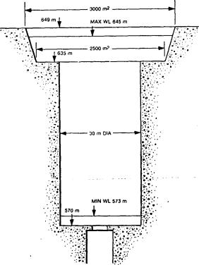
The first scheme was the most economical, and after civil and reliability engineering design studies had shown it would give the required availability and taking account of tunnel inspection times, the arrangement shown in Fig 1.37 was adopted. Maximum station water demand is 420 m3/s. The power/time criterion was the most important factor in tunnel sizing because of the need to accelerate the 2 km water column from stand still to full flow in six seconds. The system velocities were then checked and fixed by balancing the cost of various tunnel sizes and their energy losses, within the limits of previous experience, to ensure a satisfactory tunnel lining integrity and acceptable pressure surge levels. Figure 1.38 shows the optimised surge shaft design and gives the nominal design conduit velocities. Figure 1.39 shows the flow and water hammer press ures following complete trip of six turbines from full load.
4.7 Heavy load access
Because of its size and weight the generator motor is often built in-situ so that the largest loads brought to
System velocities corresponding to the extreme maximum station generating How of 420 cubic metres per second are:
10.5 m dia LP tunnel |
4.8 m/s |
9.5 m dia HP tunnel |
5.9 ms |
3.3 m dia penstock tunnel |
8.2 m/s |
2.5 m dia main inlet valve |
14.3 m's |
3.75 m dia draft tube valve |
6-4 ms |
8.25 m dia tailrace tunnel |
2.6 m/s |
Fig. 1.38 Dinorwig conduit parameters
54
It was therefore decided to arrange for the auxiliaries of the 500 MW unit stations, then being built, to be fed under lowered frequency conditions by an independent supply from a fixed gas turbine station, located Within the site and adjacent to the main power station build ings. Gas turbines, in which the high pressure exhaust from jet engines is ducted to mechanically separate power turbines, were chosen for this purpose since no other prime mover was available which was of the right size and able to reach full load within several minutes of a start. The power turbines were directly coupled to AC generators whose size was fixed by the auxiliary needs of the stations in the range 17.5 MW to 29 MW.
Such gas turbines, based on aero engine technology, are able to provide the capability for starting main generating units from cold when disconnected from the grid (called a black start) as well as adding to its output for meeting peak load demands. On nuclear power stations these units may be used to supply power to emergency reactor cooling plant and other safetyrelated equipment in the event of a reactor trip.
5.2.2 Peak load generation
With the launching of the emergency sets installed at several large power stations, the CEGB was aware of a need for turbines of large capacity which could be placed on sites of old, inefficient steam stations. The result was the development of gas turbine power
Gas turbines
stations designed to meet peak load demands con taining sets with outputs between 55 MW and 70 MW capacity which could easily be incorporated into the 132 kV network.
During times of high demand, these gas turbines are used in a system support role to back up the generation available from the major power stations. Their rela tively short start times enable generation to be added to the power network quickly. This is important in con trolling and stabilising the system frequency and in meeting sharp increases in consumer demand if there is little or no extra high merit plant capacity available.
In total, the CEGB has six gas turbine power stations currently-in operation to meet such peak load require ments, each equipped with two generating sets. The total capacity of these stations is approximately 1300 MW, comprising units of up to 70 MW with four gas generators combined together in various ways to pro duce the required output (see Fig 1.41).
Although gas turbines have the advantages of low overall capital cost and relative ease of siting close to load centres (with consequent transmission economy and suitability for remote control operation), the low thermal efficiency and high fuel costs mean that this type of unit is only economic for annual load factors of up to approximately 5%. Hence, gas turbine stations are.confined to peak lopping operations and to cope with system emergencies.
57
It was therefore decided to arrange for the auxiliaries of the 500 MW unit stations, then being built, to be fed, under lowered frequency conditions by an independent supply from a fixed gas turbine station, located Within the site and adjacent to the main power station build ings. Gas turbines, in which the high pressure exhaust from jet engines is ducted to mechanically separate power turbines, were chosen for this purpose since no other prime mover was available which was of the right size and able to reach full load within several minutes of a start. The power turbines were directly coupled to AC generators whose size was fixed by the auxiliary needs of the stations in the range 17.5 MW to 29 MW.
Such gas turbines, based on aero engine technology, are able to provide the capability for starting main generating units from cold when disconnected from the grid (called a black start) as well as adding to its output for meeting peak load demands. On nuclear power stations these units may be used to supply power to emergency reactor cooling plant and other safetyrelated equipment in the event of a reactor trip.
5.2.2Peak load generation
With the launching of the emergency sets installed at several large power stations, the CEGB was aware of a need for turbines of large capacity which could be placed on sites of old, inefficient steam stations. The result was the development of gas turbine power
Gas turbines
stations designed to meet peak load demands con taining sets with outputs between 55 MW and 70 MW capacity which could easily be incorporated into the 132 kV network.
During times of high demand, these gas turbines are used in a system support role to back up the generation available from the major power stations. Their rela tively short start times enable generation to be added to the power network quickly. This is important in con trolling and stabilising the system frequency and in meeting sharp increases in consumer demand if there is little or no extra high merit plant capacity available.
In total, the CEGB has six gas turbine power stations currcnt)y-in operation to meet such peak load require ments, each equipped with two generating sets. The total capacity of these stations is approximately 1300 MW, comprising units of up to 70 MW with four gas generators combined together in various ways to pro duce the'required output (see Fig 1.41).
Although gas turbines have the advantages of low overall capital cost and relative ease of siting close to load centres (with consequent transmission economy and suitability for remote control operation), the low thermal efficiency and high fuel costs mean that this type of unit is only economic for annual load factors of up to approximately 5%. Hence, gas turbine stations are.confined to peak lopping operations and to cope with system emergencies.