2 1 8 |
ELECTRICAL ENGINEERING |
(a)
(b)
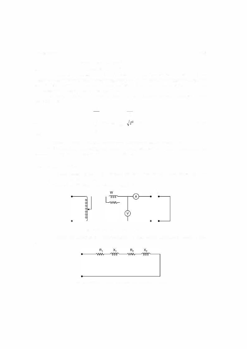
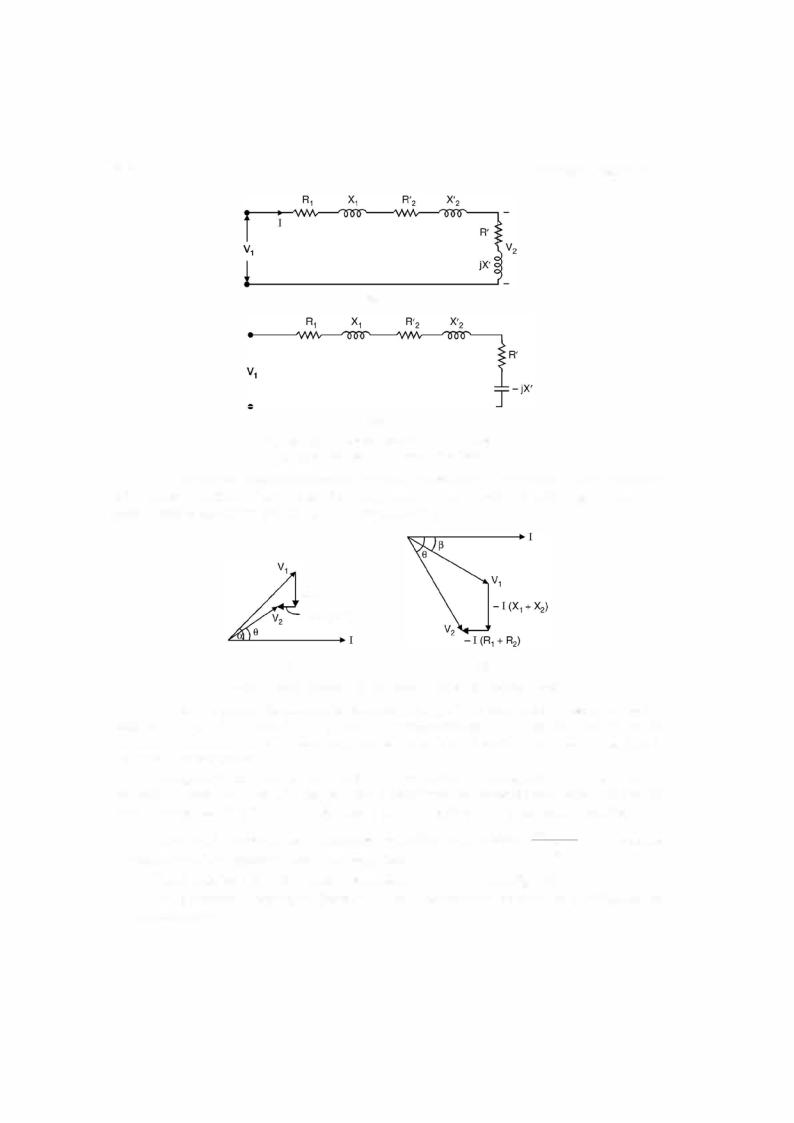
Fig. 5.16. (a) Equivalent circuit for inductive loading
(b) Equivalent circuit for capacitive loading.
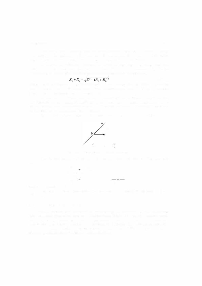
To draw the phasor diagrams for the two loadingconditionswe take V1 fixed and since it is a seriesa circuit we take Ias the reference phasor. In the inductive circuitIlags V1 by say an angle and in capacitivecircuitI leads V1 by an angle -
Io (X1 + X2)
-I (R1 + R2)
Fig. 5.17. Phasor diagram for (a) inductive load (b) capacitive load.
+ + 2
In both the phasor diagrams, the secondary voltage V is obtained after subtracting the drops due to l(R1 R2) and I(X1 X2) from the supply voltage V1 and we find that in case of
inductive load the magnitude ofsecondaryvoltage is lessthanthe supply voltage and for capaci tive loads it is otherwise.
Voltage regulation ofa transformerfora particularload is defined as the changein second
ary voltage from the no load to the load under consideration expressed as a ratio of the rated |
2 |
|
|
2 |
E |
Vz |
|
voltage ofthe load. IfE in the ratedsecondaryterminalvoltage andV is the secondaryterminal |
voltage for a particular load, then percentage regulation is expressed as |
=EzV-1z |
|
x 100 keeping |
the primary voltage magnitude and frequency fixed. |
|
E2 |
|
|
|
and |
when referred to primary side |
|
|
|
Please note that V1 ::: E1 |
E2 |
|
|
|
|
|
Let us develop an expressionforvoltage regulation making use ofthe phasor diagram for the inductive load
...(5.26)
TRANSFORMER |
|
|
|
|
|
|
|
|
|
|
|
|
|
|
|
|
|
219 |
|
V1 cos a = V2 cos 8 + I(R1 + R2) and V1 sin a = V2 sin 8 + I(X1 + X2) |
|
Let |
R1 |
+ R2 = R and X1 + X2 = X |
|
|
|
|
|
|
|
|
|
|
|
Hence |
V 2 cos2 a = (V cos 8 + IR)2 |
|
|
|
|
|
|
|
|
|
|
|
|
|
|
1 |
2 |
|
|
|
|
|
|
|
|
|
|
|
|
|
|
|
|
and |
V12 sin2 a = (V2 sin 8 + IX)2 |
|
|
|
|
|
|
|
|
|
|
|
|
|
or |
|
V12 = V22 + 2IRV2 cos 8 + 2 Vz1X sin 8 + I2(R2 + X2) |
|
...(5.22) |
|
|
|
2IR |
|
8 |
|
2IX sin 8 |
|
I |
2 |
R |
2 |
|
|
2 |
|
|
or |
|
1 --Vz |
cos |
|
V2 |
|
--V22 ( |
|
|
X |
|
) |
...(5.22 A) |
|
|
|
|
|
|
|
|
Normally ratedloadvoltage V is known, the parameter oftransformerR andXare known |
|
|
|
+2 |
|
|
|
+ |
|
+ |
|
|
|
|
+ |
|
|
|
|
and p.f. cos 8 ofthe load is also known, hence vl can be calculated and then |
|
|
|
|
|
V - |
|
|
|
|
|
|
|
|
|
|
|
|
|
|
|
% regulation = |
|
iVzVz x 100 |
|
|
|
|
|
|
|
|
|
...(5.23) |
From equation (5.22 A) exact value ofregulation can thus be obtained. However, in prac tice the last term under the square root signin equation 5.22 is generally negligible, therefore
|
= Vz ll+ |
|
2IR |
2IX . |
|
12 |
V1 |
|
|
...(5.24) |
( |
- COS S + -Slll)S |
|
|
V2 |
Vz |
J |
|
Further simplification can be made as the terms within the simple brackets is small as
|
|
|
hence usingbinomial expansion and limiting onlyto second term |
compared to unity and |
|
V1 V2 |
+ IR cos 8 + IX sin 8 |
f |
|
|
|
|
|
V1f- V2 |
IR |
-IX . |
|
or |
regulation = |
|
V2 |
= -V2 |
cos S + V2 sm S |
...(5.25) |
|
The quantity IR |
= Vris dimensionless and is known as per unit resistance of the trans- |
|
|
IX-9 |
former. Similarly |
2 V.= Vx is the per unit reactance ofthe transformer. Equation (5.25) has been |
|
|
V |
|
|
|
|
|
|
|
derived for an inductive load where |
8 is positive and hence sin 8 is positive. However, for a |
capacitive load 8 is negative and hence sin 8 is negative and hence, the general expression for regulation is givenby equation as follows
regulation = IR cos 8 ± -IX"V; sm. 8
-
V2
where plus sign is to be used for inductive load and minus sign for a capacitive load.
Fromthe equation 5.26 it is seen that the voltage regulation ofa transformercan be zero ifthe load is capacitive and the p.f. angle 8 is such that
or
or
and the p.f. is leading.
Vz |
Vz |
|
|
|
IR |
IX . |
|
|
- cos 8 - |
- |
sm 8 = 0 |
|
|
|
|
R cos 8 = X sin 8 |
|
|
sin s |
R |
x |
|
|
cosS |
X |
|
|
8 |
|
_, R |
|
|
= tan |
- |
|
|
|