

Basic_Electrical_Engineering_4th_edition
.pdf


DC MACHINES |
247 |
material and connected to the brush holder. Brushes are normally placed along the magnetic neutral axis. Brushes must be inspected regularly and replaced as necessary, as they are worn away. The emfinduced inthe conductors ofthe de machine is an alternating emf. The commuta torhelps inconvertingthis alternating emfinto direct current emf. Thisis, therefore,also known as mechanical converter.
Mainly there are two types ofwindings on the armature, the lap and the wave winding. The lap winding has the number ofparallel paths equal to the number ofpoles or no. ofbrushes. The total induced emfis the emfinduced in one path and the current delivered to the external circuit equals the current in each armature coil multiplied by the no. of parallel paths.
Incontrastthewavewindinghas onlytwo parallel pathsirrespectiveofthe no. ofpoles and hence wave winding is suitable for large voltage small currents whereas lap winding for small voltagelarge currents.
6.3EMF EQUATIONS
Ade machine maybe a de generator or ade motor. Thede generator converts mechanical energy into the electrical energy whereas a de motor converts electrical energy into mechanical energy. Ade generatorworks onthe principlethatthe motion ofaconductor (mechanical energy) through a magnetic field causes an emf to be induced in the conductor.
Howeverwhen acurrentcarryingconductoris broughtin a magneticfield and the conduc tor cuts the fluxlines (not paralled to fluxlines), a force acts on the conductor and thus torque is developed andthe electric energyisconvertedintomechanicalenergy.
The polefaces are so designedthatthe magneticfluxlines cutthe conductorsinthe arma tureslotsradially andhence whenthe armatureisrotatedwiththe help ofaprime moverthe flux lines cut the conductor and an emf is induced in the conductor which is given by
e = Blv |
(6.1) |
where e is the voltage induced in one conductor whose length is l metres and is moving with velocity v metres/sec and the conductor is moving in a magnetic field offlux density B Wb/m2. If Z is the total number ofconductors andA the number ofparallel paths, the no. ofconductors in series is ZIA. Therefore emf E generated is
z |
...(6.2) |
E = B. lv.- |
|
A |
|
Let¢ be the flux per pole,Pthe number ofpoles, the total flux inthe air gap isP<jl.This gap is in the form of a cylinder with length equal to the armature conductor length and r the radius ofthe air gap. Since the flux in the air gap is radial, the normal cross-section of the flux is the surface ofthe cylinder and equals 2rcrl
Hence flux densityB
B = 2rcrl<j>P |
...(6.3) |
IfN is the speed ofrotationofthe armature in rpm, the linearvelocity is |
|
v = N2rcr |
...(6.4) |
60 |
|


DC MACHINES |
249 |
Cork Screw rule the fluxlines encircle the conductor clockwise. However, ifthe current is coming outofthe paper, the fluxlines encircle the conductor anticlockwise. So whencurrentflowsthrough the armatureconductors it gives rise to magnetic flux. The magnetic fieldproduced dueto current carrying armature conductor distorts the magnetic field produced by the fieldpoles. This effect is known as armature reaction.
Fig. 6.3 shows a two pole de generator. Suppose the brushes are placed along the geometric neutral plane as shown in Fig. 6.3. The direction ofcurrent is given by Fleming's right handrule and accordingly it is shown in the Fig. 6.3 indicating that the current is going into the paper underthe northpole andhence the flux lines areinclockwise direction. However, under the south pole the currents are coming out ofthe paper and the netfluxlines are anticlockwise. Theresult antarmaturefluxlies alongthe geometric neutral plane (GNP) andisindicatedby OA. The main fieldfluxis ofcourse from the northpole to south pole andis indicatedby OD. The phasor sum of OA and OD gives the resultant flux OE.
Fig. 6.3. Armature reaction in a de generator.
Whenfield due to armatures conductors is not there, the magnetic neutralplane coincides withthe geometric neutral plane. However, ifthe flux due to armature conductor is present, the magnetic neutral plane will be perpendicular to this resultant field OE and is thus shifted from the GNP in the direction of rotation of the armature. The higher the loading of the generator higher is the armature flux and greater is the shift of the magnetic neutral plane. For clear understanding ofthe effect ofarmature current on the main magnetic field refer to Fig. 6.4. It is clear from the Fig. 6.4 that the mainfluxtends to increase at the trailing pole (North pole) tips and decreases at the leading pole tips. This is known as cross magnetising effect of armature reaction. The field at the trailing pole tips is strengthened andthat under the leading pole tips it is weakened. If the armature teeth were not saturated, the total flux would remain constant. However, due to saturation ofarmature teeth, it is possible that strengthening oftrailingpole tips maybe smaller thanthe weakeningofleadingpole tips. Therefore, a small amountofdemag netisation may also occur.

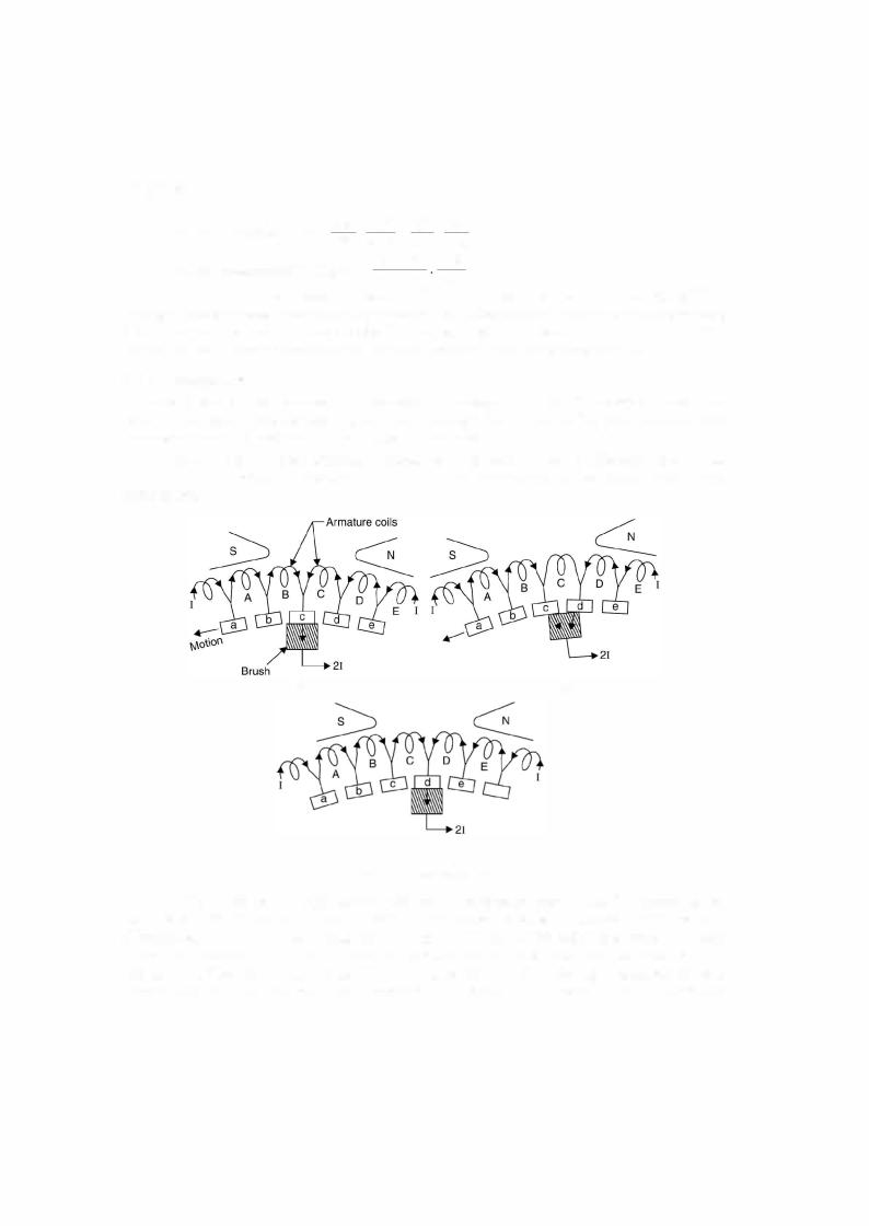

252 ELECTRICAL ENGINEERING
period of short circuit, the difference ofcurrent would go from commutator to the brush in the
formofa spark. Such sparkingcausesheating, pitting and rougheningofthe commutator surface. Suppose L is theinductance ofthe coil andthe current changes from +I to - I in a time Tc
(commutation time) a selfinduced emfL dtdi known as reactancevoltage appears and is given as
reactance voltage T2LI volts. The directionofthisinducedemfis such thatit opposes the change
in current.
c
Armature reaction and reactance voltage adversely affect the commutation process. Fol lowing are the methods to overcome commutation problem.
(i) Brush shifting |
(ii) Inter poles |
(iii) High resistance brushes and |
(iv) Compensatingwinding. |
The former two methods minimise the commutation problem due to reactance voltage whereas the latter two to armature reaction.
(i) Brush shifting. In this method the brushes are shifted by an angle slightly more than the magnetic neutral axis (due to armature reaction) so that the brushes lie in the zone of next pole. Because of this an emf is induced in the coil undergoing commutation due to the influenceofthe nextpole andthis emfcancels the reactance voltage. However, this method poses certain practical difficulties. The magnetic neutral axis itselfgoes onchanging as the loading on the machine changes as a result the armature reactionchanges. Everyloadingrequires different brush shifting and hence it is not a practical method.
(ii) Inter poles. Fig. 6.7 shows inter pole in a de generator. These are also knownascommutatingpoles. These are small auxiliary poles situated between the main poles. For a generator an inter pole should have polarity which is the same as that ofthe next main pole. These commutating poles induce an emfin the coil undergoing com mutationwhichopposes andhence cancelsthereactancevoltage. Since the reactancevoltage is proportional to the armature current, the in ter poles are connected in series with the armature circuit. It is to be noted that the commutating field should be of proper magnitude. It shouldneitherbe too strongnor too weak. Ifitis too strongit will over compensate the reactance voltage and the arc will be in the reverse direction and this is known as over commutation.
(iii) High resistance method. The use of brushes having high contact resistance im proves the commutation. In Fig. 6.6 the brush is making contact with commutator segments c and d. Whenthe currentfrom coil B reaches segment c, itflows partly through coilc and segment d andpartly direct to thebrush. Ifthe contact resistance is high, more and more current tends to flow through the first path i.e. via coil C. This is due to the fact that the area of segment c in contact with brush is decreasing and the area ofsegment d in contact with brush is increasing. This process thus improves commutation. The use ofcarbon andgraphiteforthe brush material provide high contact resistance and is used in all de machines.
(iv) Compensating winding. In heavy duty de machines the change in armature cur rent may be large whichwould cause large and sudden change in flux and induce a high emfin
