

Basic_Electrical_Engineering_4th_edition
.pdf1 54 |
ELECTRICAL ENGINEERING |
2 V
4 V -=- |
2s n |
|
|
1 0o n |
|
|
Fig. P2.2 |
2.3. |
|
[Ans. 26.7 mA] |
Determine the current in all the branches ofthe network shown in Fig. P. 2.3 using loop analysis. |
||
|
20 Q |
1 1 Q |
-=- 75 V
2 0 6 0
|
Fig. P2.3 |
2.4 |
[Ans. 1.844 A, 2.787 A, - 0.246A] |
In the network shown determine the current using loop analysis. |
40 V -=-
2 0
3 0
-=- 25 v
6 0
Fig. P2.4
[Ans. 8.32 A, 6.32 A, 4.56 A]

NETWORK THEORY |
1 55 |
2.5. |
Findthe currents Jl' 12 andJ3 andthe voltage V1 and V2 inthe given network using nodal analysis. |
||||||||||||||||||
|
|
|
|
0.3 Q |
|
|
0.1 Q |
|
13 |
|
|
|
|
|
|
|
|
|
|
|
120 v -=- |
|
30 A |
|
V220 A |
|
|
|
|
|
|
|
|
|
|
|
|||
|
|
|
|
|
|
|
-=- 1 1 0 V |
|
|
|
|
|
|
|
|||||
2.6. |
In the network shown in P. |
|
Fig. P2.5 |
s o= |
|
= 13 = |
|
|
= |
|
|
|
|
= |
109 V] |
||||
|
4 0 |
40A, 12 |
|
V1 |
|
|
V, V2 |
||||||||||||
|
|
|
|
[Ans. |
I1 |
|
|
|
|
lOA, |
|
112 |
|
||||||
|
|
|
2.6 determine currents in various branches using nodal analysis. |
||||||||||||||||
|
|
30 v - = - |
2 0 |
|
-=- 40 v |
|
|
|
|
|
|
|
|
|
|
||||
|
60 V = |
5 Q |
Fig. P2.6 |
|
|
|
|
= |
|
|
|
= - |
|
|
|
= |
|
||
2.7. |
= 40 V |
|
|
[Ans. 11 |
3.42A, |
|
4.74, |
13 |
8.16 A] |
||||||||||
|
|
|
|
|
|
|
|
|
|
|
|||||||||
In the networks shown determine the branch currents using nodal |
analysis. |
|
|
|
|
|
|
||||||||||||
1 0 Q |
J2 |
|
|
|
|
|
|
|
|||||||||||
|
15 Q |
|
20 Q |
|
|
|
10 Q |
|
|
|
- 50 V |
|
|
|
|
||||
|
|
(a) |
|
|
|
|
|
|
10 Q |
|
|
|
|
||||||
|
|
|
|
|
|
|
(b) |
|
|
|
|
|
|
|
|
|
|
||
2.8.
55 v
|
|
|
Fig. P2.7 |
(a) and (b) |
|
|
|
|
|
|
|
|
|
[Ans. (a) 2. 74, 1 .05, 79 A, |
(b) 5A, OA, 5A] |
||||
Determine the branch current in the networks shown using nodal |
analysis. |
55 Q |
|
||||||
45 Q3. |
|
|
|||||||
3 0 |
4 Q |
S Q |
35 0 |
|
70 Q |
-=- 50 v |
|||
- = - |
8 Q |
7 Q |
-=- 50 v |
55 v -=- |
80 Q |
|
|||
|
(a) |
|
Fig. P2.B |
(a) and (b) |
|
(b) |
|
|
|
|
[Ans. |
5.866, |
1 . 1 9, 4.675, ::l.472, 4.662, |
(h) 0.988, 0.66 1 , 0.277, 0. 1 089, 0.7705] |
|||||
1 56 |
|
|
|
|
|
|
ELECTRICAL ENGINEERING |
2.9. |
Determine the difference of potential between the points X and Y in the network shown. |
||||||
|
|
|
|
2 Q |
|
x |
5 Q |
|
|
|
|
2 V |
|
|
|
|
|
|
|
|
|
|
y |
|
|
|
qu |
|
|
Fig. P2.9 |
|
|
|
|
|
|
|
[Ans. Yis 3.7 V + ve w.r.t. X] |
|
2.10. |
Determine the e |
ivalent (a) The |
enin s and (b) Norton's circuits which may be used to repre |
||||
|
sent the given |
|
|
v2 Q |
' AB. |
2 Q |
|
|
|
network at the terminals |
|
||||
Fig. P2.10
|
|
n |
|
[Ans. (a) 5V 2.25 Q (b) 2.22 A, 2.25 Q] |
||
2.11. Determine the current through 3 |
resistor branch as shown in .Fig. |
|
2.11 using (a ) Thevenin's |
|||
theorem (b) Norton's theorem. |
|
7 Q |
3 Q |
P |
|
|
|
2 Q |
|
|
|||
Fig. P2.11
3.03 A]
2.12.Determine the equivalent circuit and the current in RL by (a) Thevenin's theorem (b) Norton's theorem, E is 100 V and all resistors in the circuit have the value of 20 !1. [Ans.
Fig. P2.12
[Ans. 0.385 A]
NETWORK THEORY |
1 59 |
2.20. Determine the current through the branch |
a b using Thevenin's theorem and superposition |
theorem. |
|
|
|
|
|
|
|
|
|
5bV |
|
|
|
|
|
|
|
|
|
|
|
|
|
|
|
|
|
Fig. P2.20 |
|
|
|
|
|
[Ans. 10.62 A] |
|||||
2.21. |
|
|
|
|
|
|
|
|
|
|
|
|
|
|||||
A load of (20 - j)\,) is supplied from a source of 10 V rms and internal impedance |
(10 + j20). |
|||||||||||||||||
|
Determine the value of |
|
|
for maximum power supplied to the load and determine this power. |
||||||||||||||
2.22. |
|
|
|
|
|
|
|
|
|
|
|
|
[Ans. 20 |
|
2.22 |
W] |
||
Two reactors each of 50 Q reactance and negligible resistance are connected in series across a |
||||||||||||||||||
|
|
|
|
Xe |
|
|
|
|
|
|
|
|
|
|
|
|
|
|
|
200 V 50 Hz supply. Determine the value of resistance to be connected in parallel with one of the |
|||||||||||||||||
|
|
|
|
|
|
|
|
|
|
|
|
|
|
|
n, |
|
|
|
|
coils for maximum power dissipation. |
|
|
|
|
|
|
|
[Ans. 25 Q] |
|||||||||
2.23. |
A source ofvoltage 2 |
J2 |
sin 2t has an internal impedance |
|
Q and |
|
|
|
It is connected |
|||||||||
|
to a load having parallel combination of |
C and resistance of |
lQ. Determine C for maximum |
|||||||||||||||
2.24. |
power consumption in 1 |
Q load resistance. |
|
R l |
|
L |
= |
l/:=lH. |
[Ans. |
|
F] |
|||||||
ln the circuit shown |
|
|
is variable between 2 Q and 55 Q. What value of |
results in maximum |
||||||||||||||
|
power transfer to the load |
RL |
? |
|
= |
|
|
|
|
|
|
113 |
|
|||||
|
|
RR |
|
|
|
|
|
|
|
RR |
|
|
|
|
|
|
||
1 00L0°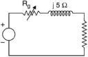 1 0 Q
1 0 Q
Fig. P2.24
[Ans. 8.66 Q, 268 W]

CHAPTER
3Three Phase Supply
3.1THREE PHASE CIRCUITS
The use of d.c. for day to day application is much older than that of a.c. The first Central Electric Station was installed by Edison in New York in 1882 which operated at 110 V d.c.
Theuse oftransformers for transmitting power over longer distances and higher voltages
justified the use of 3-phase a.c. especially when the source of energy is at a far off place from the place of load centers and the power to be transmitted is in terms of thousands of MW.
A 3-phase circuit is more efficient, reliable and cost effective as compared to 1-phase system. A 3-phase circuit would obviously require a 3-phase supply. Hence a brief review of how 3-phase voltages are generated will not be out of place even though the book is only on analysis aspects of 3-phase circuits.
Generation of 3-phase voltages is also based on Faraday's laws of electromagnetic in duction. Here the coil where the voltage is induced, is stationary whereas the magnetic field of
the constant magnitude is made to rotate. This arrangement is preferred as the voltages in
duced are in terms of kilovolt and the currents to be handled by the winding are of large magnitude depending upon the size of the generator. The largest size of the generator (3- phase) inthiscountryis of500MWcapacity. Therefore, this winding is made stationary whereas the field winding which normally operates at relatively much lower voltage and currents is made rotating.
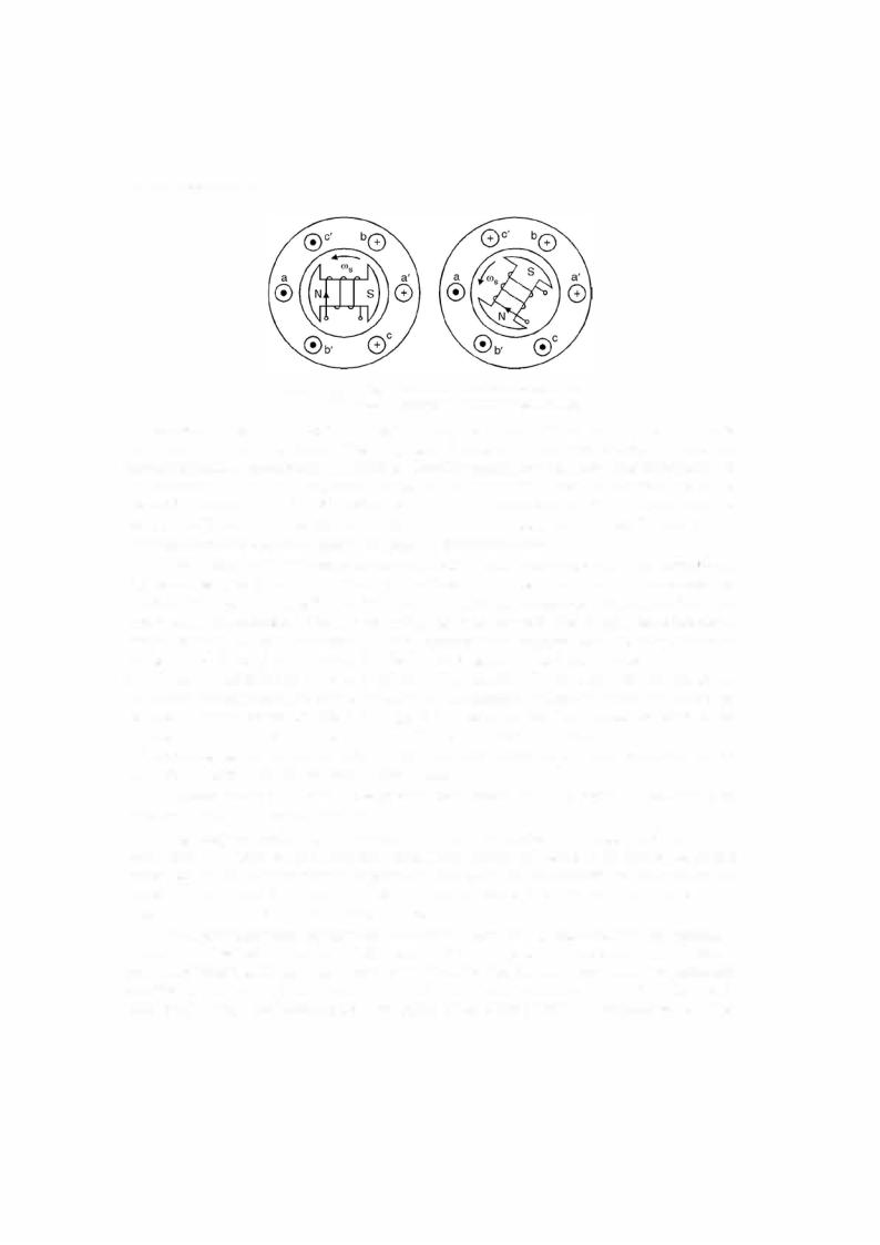
l<J.g. 3.1 shows an elementary 3-phase generator or alternator. Fig. 3.1 shows a two-pole rotor, the field winding of which is fed from a d.c. source to create magnetic flux for the poles. The poles are so shaped that these produce sinusoidal flux in space. The stator has a balanced three-phase winding with the axis of each phase displaced by 120°. The stator winding is balanced ifthe machine is mechanically symmetrical and ifthe electricalcharacteristics ofthe three coils are identical. The complete winding is represented in Fig. 3.1 by a single coil for simplicity.
Now, if the rotor is driven by a prime mover in the anticlockwise direction as shown, at synchronous speed, the voltage induced in the coil will be u x Bl and the direction of emf. induced will be given as per Flemmings right hand rule or by the cross product u x B rule.
With this rule the induced emf. in the coil sides a b' c' is directed outside the paper whereas in coil sides a'bc it is directed into the paper. Also since coil side a and a' are located alongthe pole axiswheretheflux densityis maximum, theinducedemf.inphase 'a' is maximum.
1 60
THREE PHASE SUPPLY |
1 61 |
Fig. 3.1. (a) Voltage induced when pole axis along aa'
(b) Voltage induced when pole axis along bb'.
The corresponding emf. induced in phase b as identified by coil side b is found to he ofopposite sign and of smaller magnitude. The magnitude is smaller as the flux density at the same instant is smaller as compared to what it is along the axis ofthe pole. In fact the distribution of B is cosinusoidal when it is maximum along the axis aa', it will have a value B/2 along bb' as the angle between a and b is 60° and cos 60° = Yi. A similar reasoning yields the same results for phase c. It is to be noted that the angles given here are electrical degrees. However, for a two pole rotor, the electrical angles are equal to mechanical angles.
Next consider that the rotor has advanced 60° in counterclockwise direction. Now, North Pole coincides with b' and south pole with b indicating that the induced emf. is now a negative maximum in phase b. In the first position it was - Vm/2 now it becomes - Vm. Also coil cc' now comes under the influence of flux of reversed polarity as shown in Fig. 3.l(b). Hence the direc tion ofthe induced emf. in c is now out ofthe paper and into the paper for c'. The instantaneous values of the three phase voltages for the first and second time instants are shown in Fig. 3.2(d) and are identified as t1 and t2 respectively. By repeating the procedure as outlined above for various instants and plotting the results for each instant of time we obtain the curves for the three phases as shown in Fig. 3.2 (a)-(c). It is to be noted that the differences between the voltages of the three coils is not in the amplitude or waveform or the frequency but a time difference between the three waveforms. One complete rotation of the rotor gives one cycle of the voltage wave as shown by dotted vertical line.
Physical connection of the ends of each phase (points a', b', c') gives a Y-connection or Wye connection of the stator winding.
Fig. 3.2(d) shows the typical pattern of three phase system of voltages when the three waveforms are drawn on the same time axis. These waveforms can also be developed as the projections of the rotating phasor as shown in Fig. 3.2(e). In our analysis we will always as sume that we have a 3-phase supply i.e. the three voltages Ea'a, Eb'b and Ec'c are equal in magnitude and displaced in time phase by 120°.
In a basic alternator the three coil ends a', b', c' are tied together and brought externally to a common lead called the neutral N. Leads a, b and c are brought externally to line termi nals called phase a, phase b and phase c as shown in Fig. 3.3. The three phase voltages are specifically 120° apart. First phase a has positive maximum value, next phase b has its maxi mum positive value and another 120° time apart phase c has a positive maximum value. Ifthe

