

Basic_Electrical_Engineering_4th_edition
.pdf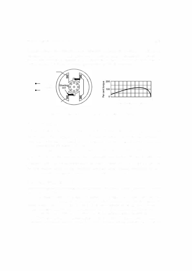
SINGLE PHASE INDUCTION MOTORS |
337 |
Horse power
-0 Q) Q) Cl.
(/)i
Torque ------ |
. |
Fig. 9.11 Characteristics of universal motors.
kinds of a.c. motors operating at the same frequency. Their starting torque is relatively high. These characteristics make universal motorsidealfor devices such as hand drills, hand grinders, food mixers, vacuum cleaners and the like which require compact motors operating at speeds greater than 3000/3600 rpm. Universal motors must be designed with weak magnetic fields to minimise commutation difficulties. High resistance carbon brushes are used tolimitthe circulat ing current due to the transformer voltage in the short circuited coils.
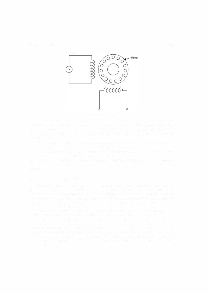
9.6SYNCHROS
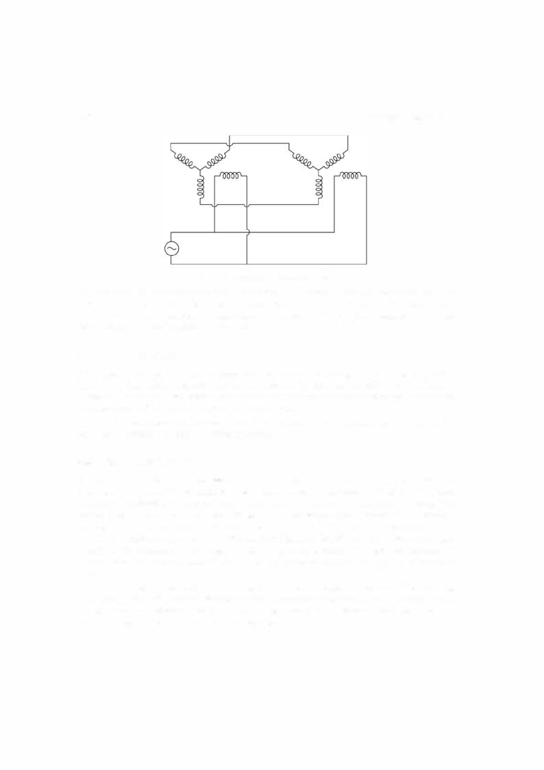
The terms synchros and Selsyn (abbreviation ofselfsynchronisation) areboth used to refer to a special wound rotor induction motors which are used in pairs to provide shaft position control and/or synchronism oftwo remote machines. Applications varyfrom controlling valves to indicat ing the position ofsome remote devices. Usually the primary winding is a single phase winding located on the rotor whereas the stator has a three phase winding which acts as the secondary whereas usual standard wound rotor induction motors could be used for the purpose, synchros usually have low inertia and low friction bearings to reduce error and mechanical dampers to improve dynamic performance. Fig. 9.12 shows application of synchros for low torque require ments. Here both the rotors are supplied from the same a.c. source. An unbalanced set ofthree single phase voltage (in time with the single phase rotor voltage) will be induced in the stator phase windings ofboth the machines. Thesevoltageswillbe equal ifandonlyifthe tworotors are exactly in the same position. Assuming one machine is the transmitter, its rotor position will be fixed by the controlling mechanical input. If the rotor of the other machine is considered as receiver and ifit is not at the same position, unequal phase voltages will exist. This will result in statorcurrent, thus mmfandthe torque seeking to alignthe receiver'srotorposition withthat of the transmitter.
Equilibriumis reached when the outputtorque decreases to equal the torque requiredby thetransmitter's load. Therefore, it is necessarythatthe load torquebe smallandthatfrictionbe minimised in the synchros.
Synchros are also constructed with three phase rotor windings. For low torque applica tions, itis commonto supply bothtransmitter andreceiver stator windings from the same three
338 |
ELECTRICAL ENGINEERING |
Fig. 9.12. Low-torque synchros system.
phase source. The rotor windings are then connected in parallel. Again by Faraday's law, flux distribution must be the same in both the machines. Equilibrium will exist in the rotor circuit only when the rotors are synchronised at the same relative positions. Otherwise, a torque will be produced which tends to align the two rotors.
9.7DC TACHOMETER
Itis sometimes necessaryincontrol systemstofeedback a voltage proportionaltothe speedofthe shaft. In a d.c. servomechanism this can be achieved by using a d.c. tachometer which is a permanent magnet d.c. generator. The field is due to permanent magnet which ensures that the voltage output willbe directly proportional to the speed.
A d.c. tachometer can be used on a.c. servomechanism by converting the d.c. outputvolt age to an a.c. voltage by using an inverter circuit.
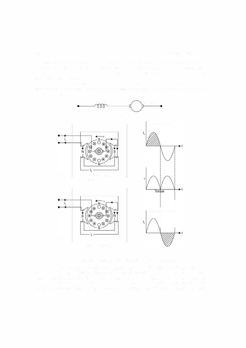
9.8AC TACHOMETER
An a.c. tachometer is used infeedback control system to feedback an a.c. voltage proportional to the speed ofthe shaft. This is basically a two-phase induction motor as shownin Fig. 9.13. One of the stator windings is used as the reference winding and the other the control winding. The reference windingisfed a suitable a.c. voltage ofconstantfrequency and magnitude. Therefore, a voltage ofthe same frequency is induced in the control winding. This output voltage is fedto the highinputimpedance circuitofanamplifiersothat thecontrolwindingcanbe considered as open circuited. It is essentialthatthe voltage inducedin the controlwindingis directly proportionalto the shaftspeed and phase ofthis voltagebe fixedwithrespect to voltage suppliedto the reference winding.
The principle of operation of an a.c. tachometer can be explained using double revolving field theory. Withreference to reference winding the tachometer can be considered equivalentto a single phase induction motor. At standstill, the forward and backward fields are equal and hence voltage induced in the controlwindingis zero.
SINGLE PHASE INDUCTION MOTORS |
339 |
Reference winding
Control winding
Fig. 9.13. AC tachometer.
Whenthe rotor is revolving, the rotor current due to forward rotating field decreases since itseffective impedance increases whereas forthe backward rotatingfieldtheimpedance decreases, the differencebetweenthembeingfunction ofspeed. Therefore, thevoltage developed across con trol winding is a function ofspeed. Reversal ofdirection ofrotation reverses the phase ofoutput voltage.
For a constant phase angle of output voltage and linear relationship between outputvolt age and speed, a suitable value ofratio ofrotorreactance to rotorresistance should be chosen. If it is low, the sensitivityi.e. volts per revolutionper minute is sacrificed but linear speed range is wide. However, ifit is high the speed range is limited to a fairly small fraction of synchronous speed to meet the condition oflinearity ofvoltage and consistency ofphase angle. An a.c. tachom eter shouldhave lowinertiawhenrapid speedvariations are encountered as inautomaticcontrol system.
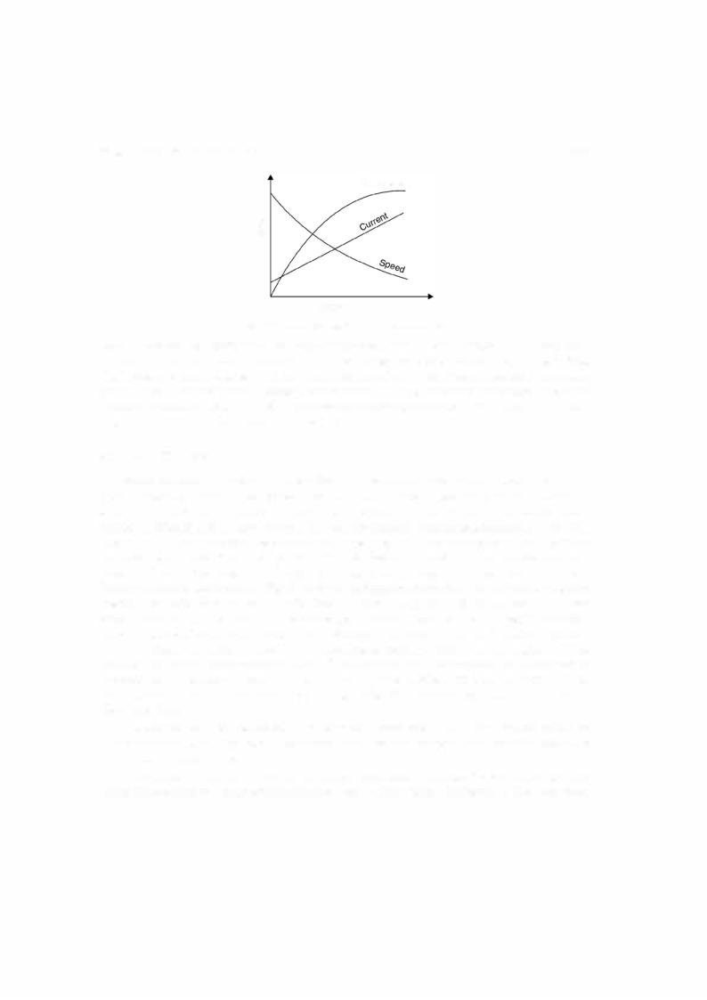
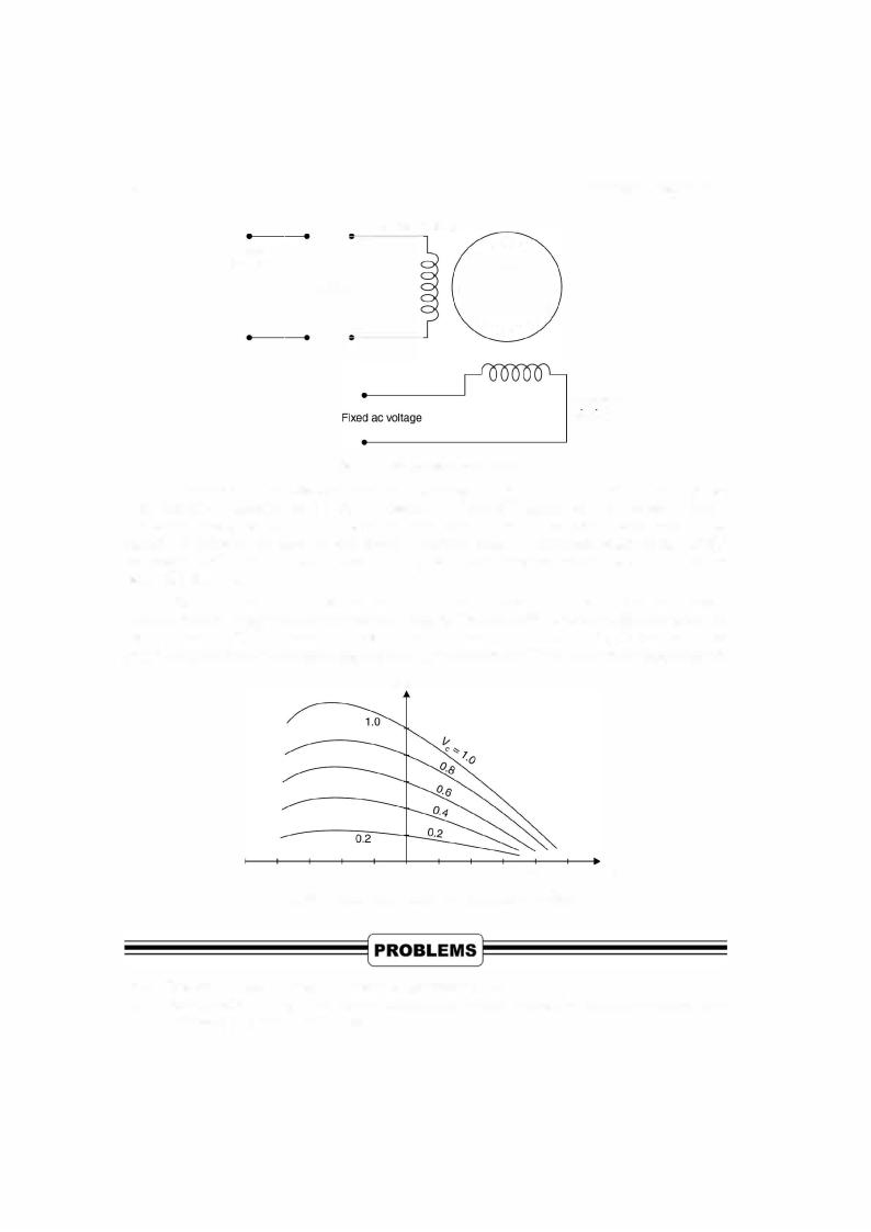
9.9 TWO PHASE SERVOMOTOR
Atwo-phase servomotor is commonly used infeedback control system to drive the loads and as sensorsto measure speed andpositionofthecontrolled element. Itisbasicallya two-phase induc tion motor with squirrel cage rotor. The rotor has high resistance so that a negative slope (in crease intorqueresults decreasein speed andviceversa)forthetorquespeed characteristics over the entire operating range is obtained The negative slope characteristic provides stable operation and positive damping. The ratio of rotor diameter to its length is small so that its moment of inertia is small andhence it gives good acceleration characteristic. The motor is quite rugged and reliable and is used in different range from a fraction ofa watt to about hundred watts.
Fig 9.14 shows schematicdiagram ofa 2-phase servomotor. One ofthe stator windings is known as a reference winding and is excitedby afixeda.c. voltage Vr whereas the second winding known as control winding is excited by the control voltage Ve For production of torque it is necessary that the two voltages should be in synchronism. Hence the two voltages must be de rivedfromthe same source. The control voltage is fed to the motorthroughan amplifier. Alsothe two voltages must have a phase difference of90° (balance 2-phase operation where the torque is maximum).

SINGLE PHASE INDUCTION MOTORS |
341 |
9.3.Describe how to reverse the following single phase induction motors (a) Resistance split phase
9.4.(b) Capacitor start (c) Permanent slip capacitor (d) Two value capacitor (e) Shaded pole motor. A single phase induction motor has poor performance as compared to a 3-phase induction motor.
9.5.Discuss the reasons.
Discuss the differences between capacitor start, capacitor start capacitor run and permanent
9.6.split capacitor motors.
vVhat is a universal motor ? Explain with neat diagram construction, principle of operation and
9.7.application of the motor.
What is a two-phase servomotor ? Give its application. Draw the connection diagram and its
9.8.speed torque characteristic.
9.9.Explain what you mean by stable operation of a two-phase servomotor and how it is achieved. What is a synchro ? Explain with neat diagram the working of a synchro transmitter system and
9.10.give its application.
Discuss the function of an a.c. tacho-generator. Explain with neat diagram the construction and principle of operation.
POWER SYSTEM |
343 |
Distributors |
Distributors |
Fig. 1 0.2. A Typical Distribution System.
The distribution system occupies an important place in any electric power system. The effectiveness with which it achieves its objective of distributing electric energy to various con sumers, is measured in terms ofvoltage regulation, flexibility, security ofsupply efficiency and cost.
1 0.2 TYPES OF DISTRIBUTION SYSTEM
Dependinguponthe type ofsupply, distribution system can be classified as follows :
(i)a.c. single phase (single phase loads only);
(ii)3-phase, 3-wire (3 phase loads only); and
(iii)3-phase, 4-wire (all types ofloads).
The distribution system can also be classifieddependingupon the connections. These are the following two systems :
(i)Radial system and
(h)Ring Mains system.
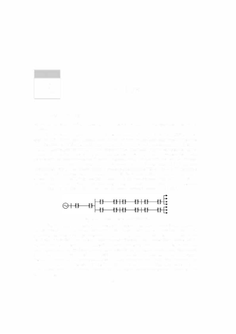
10.2.1 The Radial Systems
The electric energy distribution originally was through radial system. Atypical radial distribu tion system is shown in Fig.
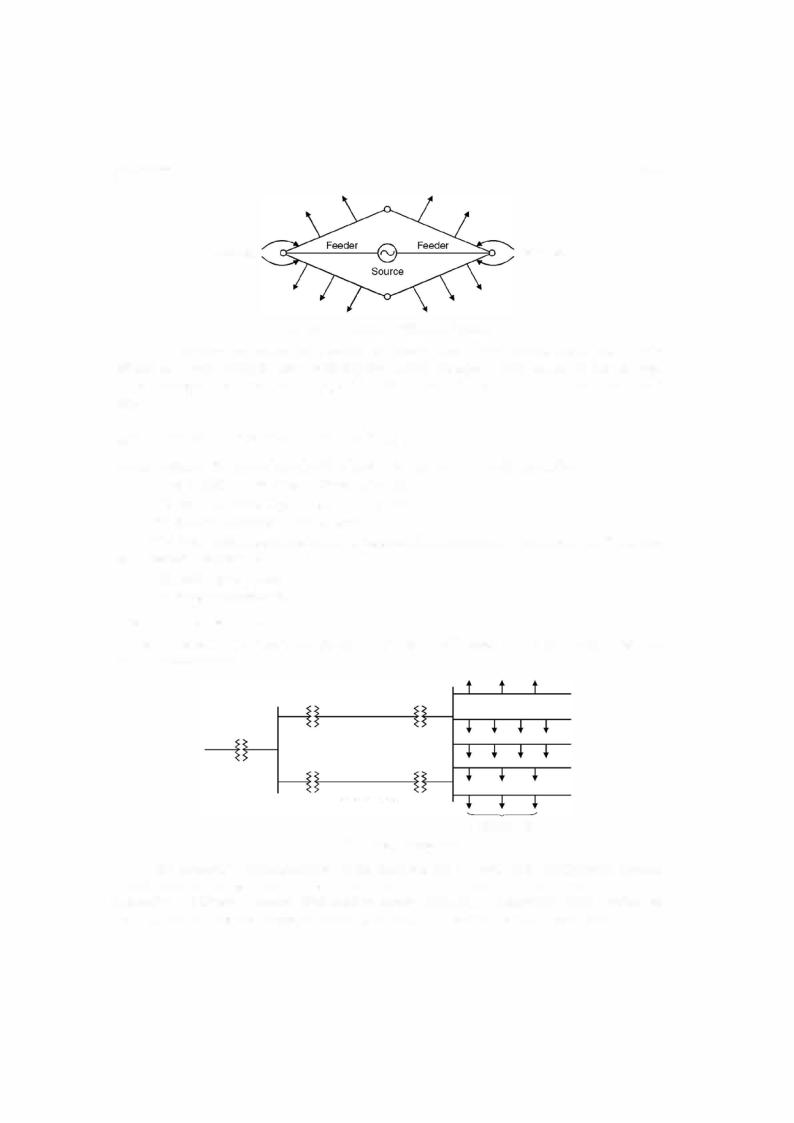
Radial feeders
Radial distributors
Fig. 10.3. Radial Distributors.
The advantages ofradial system are its simplicity and lowcost, whichresultfroma straight forward circuit arrangement where a single orradial path is providedbetweenthe consumer and the source orbulkpower supply. With such an arrangement, the amount ofswitchingequipment required is small andthe protective relayingis simple. The major disadvantage ofradial system