

Basic_Electrical_Engineering_4th_edition
.pdf1 84 |
ELECTRICAL ENGINEERING |
Whenthe meter is used as an ammeter Fig. 4.1 (a) or as avoltmeterFig. 4.1 (b), the torque of the meter is proportional to the product if the flux of the fixed coil (FC) and the flux of the moving coil. The scale ofthe instrument is thus a square one as shown in Fig. 4.l(e).
|
High |
a |
resis |
(FC) |
(FCb) |
|
tance |
Fig. 4.1 . (a) An ammeter (b) A voltmeter.
(e)
Fig. 4.1 . Typical meter scales : (c) linear, (d) zero center, (e) squared.
Since energy mustbe used to create two magnetic fields, the electrodynamometer move ment is less sensitive as compared to that in PMMC instruments.
The control torque is provided by spring torque. The damping is provided by either eddy currents or air piston attached to the pointer.
These instruments are not in common use as
(a)They have low torque/weightratio
(b)Owing to TD oc 12, the scale is non uniform
(c)These are expensive.
BASIC INSTRUMENTS |
1 85 |
4.3MOVING IRON TYPE
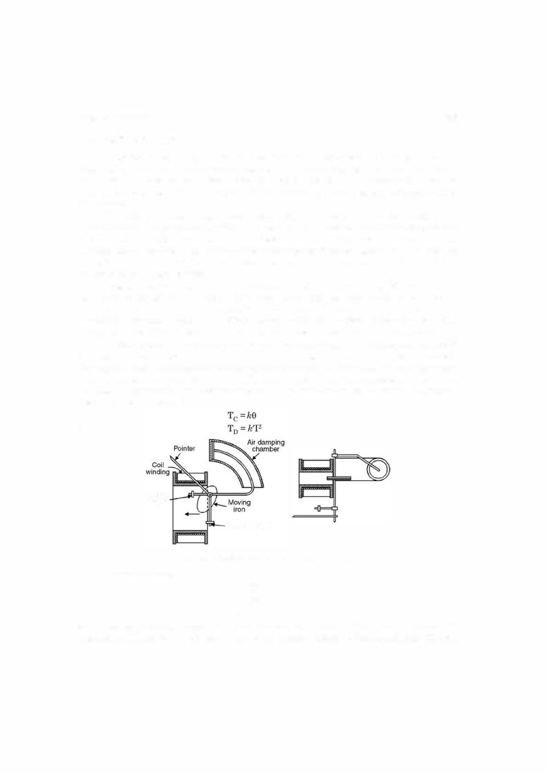
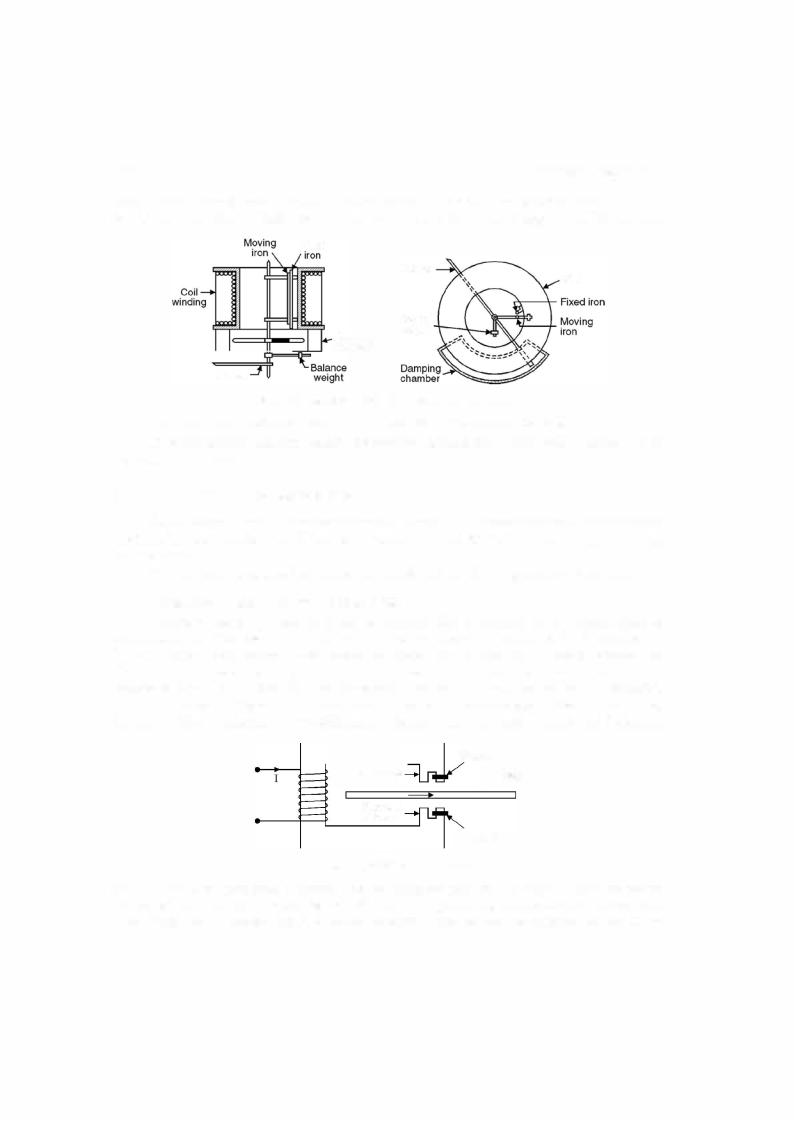
There are mainlytwotypes ofmovingironinstruments (a) Attractiontype Fig. 4.2 and (b) Repulsiontype Fig. 4.3. In these instruments thecurrenttobe measured orcurrent proportional to the voltage to be measured is passed through a coil ofwire, the no. ofturns on which depends upon thecurrentpassingthroughit. Acertainnumber ofampereturns isrequiredto operatethe instrument.
When current flows throughthe coil, a small piece ofiron is drawn into the core ofthe coil in case ofattraction type ofinstruments. In the repulsiontype, there are two rods or pieces ofiron inside the coil one are fixed and are movable. These are similarly magnetised when currentflows through the coil and repulsion of the moving iron from the fixed one takes place. The force of repulsion is roughly proportional to square ofthe rms value ofthe current as both magnets are magnetised by the same current.
Whateverbe the directionofcurrent throughthe coil, these are so designed that attraction takes place in case ofattractiontype ofinstruments, similarly repulsion takes place inthe repul sion type ofinstruments. These are therefore known as unpolarised instruments in contrast to moving coil permanent magnet type ofinstruments which are polarised. Ifthe direction ofcur rentthroughthe PMMC instrument is changed, the deflection goes inthe opposite direction.
Earlierthecontroltorque was providedbyattachingaweightto the movingiron andhence due to gravitythe control torque is obtained. But now almost universally spring control is used. The dampingtorque inthe movingiron instrument is providedby airfriction. Two different types of damping chambers have been shown in Fig. 4.2 and 4.3. The control torque is proportional to the angle9 throughwhichthe pointer moves and the deflectingtorqueisproportionalto square of the current being measured i.e.
and
Balance
weight
|
Control weight |
|
Fig. 4.2. Attraction type of moving-iron instrument. |
|
Hence atbalance |
|
TD = Tc |
|
k'l2 = k9 |
or |
9 oc I2 |
and, therefore, the scale in case ofMI instruments is non uniform. In fact iftwo meters one MI and another PMMC is placedbefore us and we are askedto identify looking at the scale. The one
BASIC INSTRUMENTS |
1 87 |
are displacedin time because ofthe copper band and are displacedin space as these are from two different parts of the electromagnet. In the induction cylinder type ofinstruments the time dis placement is obtained by inserting resistance in one circuit and inductance/capacitance in an other circuit and space displacementis obtainedby having windings on differentpair ofpoles. In order to obtain uniform torque in the disc it is usually not circular but is spiral shaped. This is dueto non-uniform torque providedbythe springtorquewhichincreases as the disc moves due to tightening actionofthe spring. The scale is usually cramped atthe lowerend since the deflecting torque is proportional to the square ofthe current or voltage to be measured and spring control is used.
|
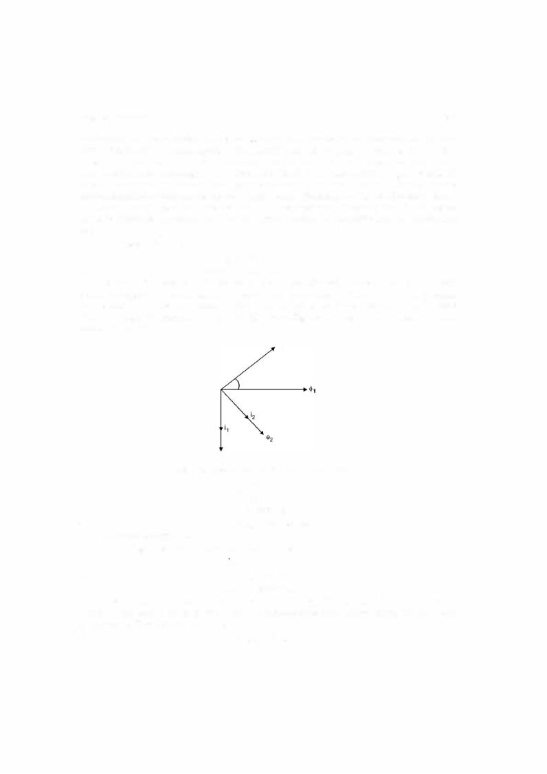
Let the two fluxes be |
= <Pm sin mt |
|
<jJ1 |
|
and |
<jl2 |
= <Pm' sin (mt + a) |
Flux<jl1 is due to shadedpole whereas<jl2 due to unshaded pole. The two fluxes<jl1 and<jl2 will induce voltages e1 and e2 respectively in the disc due to induction. These voltages will circulate eddy current in the disc. Assuming the disc to be non-inductive, these currents will be in phase withtheirrespective voltages. The phasor diagram in Fig. 4.5 shows the phase relationbetween various quantities.
2
a
|
|
|
|
|
|
e, |
|
|
|
|
|
|
|
|
|
|
|
|
|
|
|
|
|
|
|
Fig. 4.5. Phasor diagram for induction instrument. |
|
|
|
||||||||||||||||||
|
|
|
|
|
|
|
e1 |
|
dt |
|
|
|
|
|
|
|
|
|
|
||||
|
|
|
|
|
|
|
|
|
|
|
|
<P |
1 |
|
|
|
|
|
|
|
|
|
|
and |
|
|
|
|
|
|
i2 |
oc |
<Pm OJ COS OJt |
|
|
|
|
|
|||||||||
|
|
|
|
|
|
<P m' OJ cos (mt + |
|
|
|
|
|
||||||||||||
<Pl' |
|
|
e1. |
|
e2 |
oc |
<P m'm cos |
(mt + a) |
2 |
1 |
|
2 |
|||||||||||
|
|
|
|
|
|
|
|
|
|
|
|
|
i2 |
|
|
|
|||||||
The eddy current i1 |
|
|
|
|
of eddy currents |
|
|
|
|
||||||||||||||
Assuming same resistance to flowi2 oc e2 |
|
1 |
|
|
1 |
iz |
|
|
|
|
|
|
|||||||||||
and |
|
|
|
|
|
|
|
o |
= |
|
2 |
|
|
|
|
a) |
|
|
|
||||
|
|
|
|
|
|
i 1 |
|
|
m |
|
|
|
|
|
|
|
|
|
|||||
|
|
|
|
|
|
oc <P |
OJ cos mt |
|
|
|
|
|
|
||||||||||
|
|
|
|
|
|
|
|
|
= |
|
|
|
|
|
|
|
|
|
|
|
|
|
|
The flux |
|
will interact with eddy current |
|
and <jl |
will interact with i |
and since <jl is |
|||||||||||||||||
leading <jl1 the torque due |
to <jl |
2 |
and i |
1 |
will be reckoned as positive where as that due to <jl |
1 |
and |
||||||||||||||||
oc |
|
|
|
|
|
|
|
|
|
|
|
|
|
|
|
|
|
||||||
i2 as negative. The resultant torque is |
|
|
|
|
|
|
- |
|
|
|
|
|
|
|
|
|
|||||||
|
|
|
|
|
|
T |
|
oc |
<P |
|
i |
|
<P |
|
|
|
|
|
|
|
|
||
|
|
|
|
|
|
|
|
|
|
|
|
|
|
|
|
|
|
|
|
|
|
|
|
1 88
oc oc oc
<l> m' sin (cot+ a) <l>m co cos cot - < lm> sin cot <l>m' co |
ELECTRICAL ENGINEERING |
os (cot + a) |
(cot + a) cot cot (cot + a)
<l> m <l>m' sin a cos - < lm> <l>m' sin cos <l> m <l>m' sin
Thus the torque is maximum when the two fluxes are displaced by 90° and since leads <j>1 the rotation ofthe disc under the poles willbe from unshaded pole to the shaded pole.
NowAtbalance |
TB = Tc |
|
and smce |
Tc |
= k9 |
Hence |
k'l2 |
= k9 |
or
The damping torque is provided by a permanent magnet of high retentivity steel. The motion ofthe disc can be controlled by adjusting the position ofthis magnet.
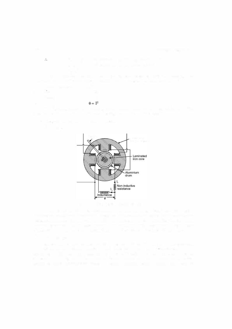
4.4.2Induction Cylinder Type Instrument
For this refer Fig. 4.6.
Pointer |
Laminated |
|
|
|
magnet system |
Fig. 4.6. Cylinder type induction instrument.
As mentioned earlier phase displacement between the fluxes is obtained by placing the windings ontwo different pairs ofpoles (space displacement) andbyplacing a high non-inductive resistance in series with one pair of winding and inductance in the other. The flux due to the windinghavingnon-inductive resistance willleadthe flux due to the otherwinding. Theprinciple ofoperation ofthe instrument is exactlyidentical to the induction disc type ofinstrument.
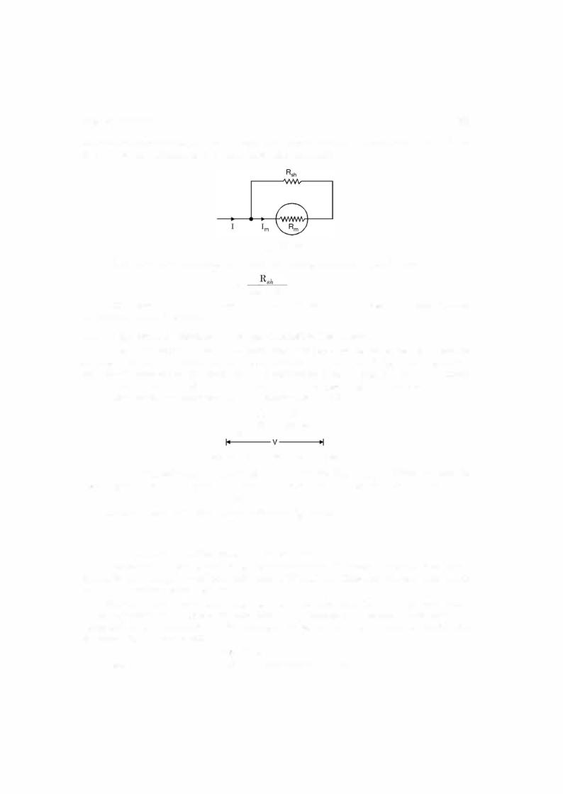
4.4.3The Shunt
Meters are available to read current in the ranges from a few microamperes to several hundred amperes full scale. However, the coil structure of the galvanometer movement is not capable of handling current greater than a few mA. Therefore when current to be measured exceeds this limiting value of coil current, the excess current must be diverted or by passed around the meter movement by means of a shunt. A shunt is a small resistance much smaller

BASIC INSTRUMENTS |
|
1 93 |
|
|
cc |
|
Source |
PC |
|
|
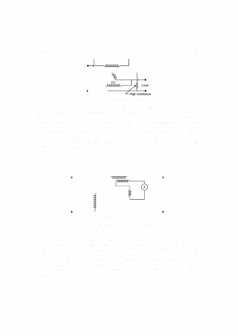
Fig. 4.9. Dynamometer wattmeter.
coil is in series with a high resistance usually designedfor two voltage ranges 220/480 volt. Since one flux is proportional to load current and the otheris proportional to load voltage, the torque on the pointer or the moving coil is proportional to the power. As a result, the power scale is not square but linear. The moving coil is carried on a pivoted spindle and the movement is spring controlled. The moving system carries a pointer and a damping vane, the latter moving in a sector-shaped box. The current coils are usually stranded or laminated especially when heavy currents are to be carried. For veryheavy currents, a low range wattmeteris usuallyemployedin conjunction with a currenttransformer. Similarly, ifthe circuitvoltage is higher than the rated voltage of the wattmeter, potential transformer can be used in between the circuit and the wattmeter.
Fig. 4.10 shows the connection ofcurrent and potential transformers in conjunction with the wattmeter. Here CT is current transformer, PT the potential transformer, CC the current coil ofthe wattmeter and PC the pressure coil ofthe wattmeter.
|
CT |
|
|
c |
|
Supply |
PT: c |
Load |
Fig. 4.10. Connection of current and potential transformers with wattmeter.
(b) Induction Wattmeter. The basic principle of operation of induction wattmeters is similar to the induction ammeters and voltmeters and can be used only on ac circuits.
Induction wattmeters have two laminated electromagnets, one is excited by the load cur rent or a fraction ofthe load current and the other is excited by the current proportional to the load voltage. A thin aluminium disc is mounted so that it cuts the fluxes from both the electro magnets and the deflecting torque is producedby the interactions between these fluxes and the eddy currents which they induce in the disc. One or more copper bands or rings are fittedon one limb ofthe shunt magnet i.e. the magnet which is energized by the current proportional to load voltage (pressure coil), sothatit causes theresultantfluxinthemagnetto laginphaseby exactly 90° behind the applied voltage. Fig. 4.11 shows the constructional details of the two types of induction wattmeters whereas Fig. 4.12 shows the phasor diagram for the wattmeter.