

Basic_Electrical_Engineering_4th_edition
.pdf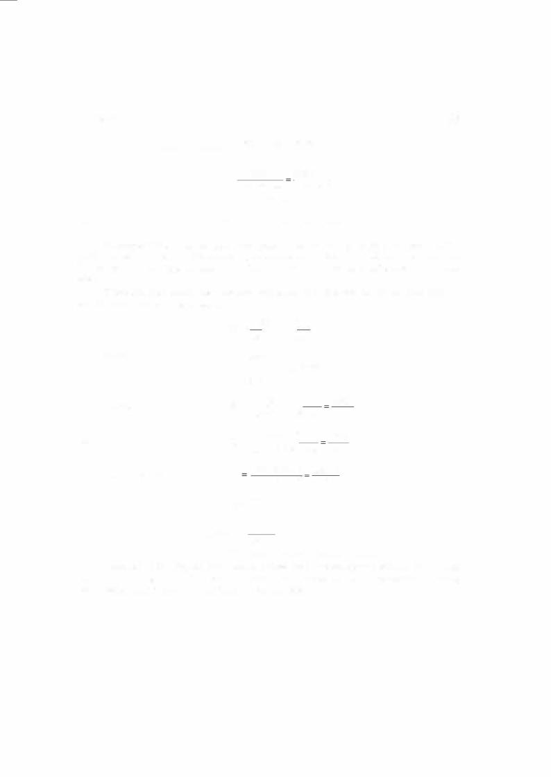

A-C CIRCUITS |
99 |
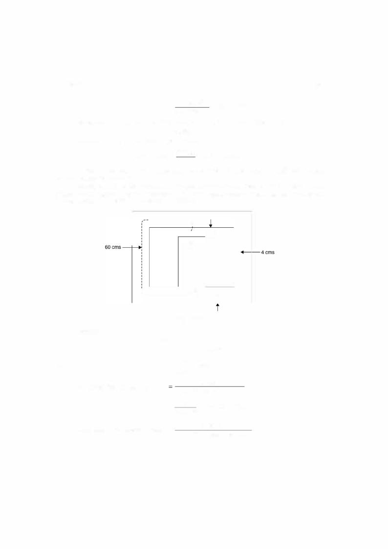
through air rather than steel core. <P |
is the flux which is linking both the windings and is |
known as mutual flux or common flux.m |
|
The total flux linking the primary winding is divided into two components (i) the result ant mutual flux confined essentially to the steel core and produced by the combined effect of the primary and secondary currents (if secondary is loaded) and (ii) the primary leakage flux which links only the primary. These components have been identified in the basic transformer in Fig. 1.26 where for simplicity the primary and secondary windings are shown on separate (opposite) legs of the core. In an actual transformer with interleaved windings (usually low voltage winding is placed near the core and then sufficient insulation is provided and high voltage is placed above the primary i.e., both the limbs have primary as well as secondary winding), the details of the flux map are more complicated but the essential features remain the same. Since the leakage path is mainly through the air, the leakage flux and the voltage induced by it vary linearly with primary current. The effect on the primary circuit is simulated by assigning to the primary a leakage inductance which by definition is equal to leakage flux linkage (leakage flux x No. of turn of primary) per unit primary current or it is equivalent to leakage reactance i.e. 2nf x leakage inductance.
Similarly the effect of secondary leakage flux can be simulated on the secondary wind ing of the transformer.
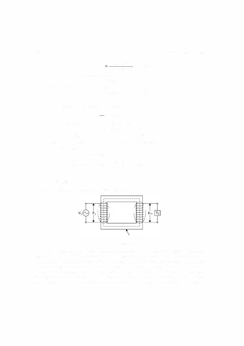
1 . 1 1 .3 Fringing of Flux
To understand fringing of magnetic flux consider Fig 1.27. In the air gap the magnetic flux line bulgeoutwards somewhat as shown in Fig. 1.27 this is known as fringing of flux. The effect of the fringing is to increase the cross sectional area of air gap. The flux density in the air gap reduce as compared to one in the core there
fore, a correction due to fringing is required. The usual correction is to add the gap dimension to each dimension of air gap e.g. ifthe
core dimensions are 3 cm by 3 cm and air gap g is 0.05 cm , the corrected area would beAg= (3 + 0.05) (3 + 0.05) = 9.3 cm2, thereby the gap reluctance decreases by about 3% for the uncorrected gap.
Fig. 1 .27 Fringing flux.
1 . 1 2 DOT CONVENTION FOR COUPLED CIRCUITS
The significance of dot convention is explained with the help of Fig. 1.28. |
|
____. |
|
Suppose a time varying voltage source is |
____. |
|
|
. |
. |
|
|
connected across the primary ofthe transformer and |
|
||
at anygiveninstant thevoltage source hasthepolarity |
|
||
shown and current i (t) is in the direction shown by the arrow and is increasing with time entering the dotted terminal, this current induces a voltage in the secondary which is positive at the dotted terminal.
Fig. 1 .28. A circuit for dot convention.
1 00 ELECTRICAL ENGINEERING
Conversely if the current in the primary is increasing and is leaving the dotted terminal this will induce thevoltage polarityinthe secondary such that the undotted endwill become positive and hence dotted terminals ofboth the windings will be negative simultaneously. The following experimental procedure can be used to establish dotted ends of the transformer windings. Mark a dot arbitrarily on one end ofthe primary winding and connect a d.c. source with positive terminal connected to the dotted end and the negative terminal to the undotted end of the winding through a switch. Connect a MC voltmeter across the secondary winding. The end of the secondary winding which goes positive momentarily on closing the switch on the primary side as measured by the voltmeter, is the terminal to be dotted.
If there are more than two windings, similar procedure can be followed for identifying
relationship between each pair of windings. For each pair of winding different forms of dots |
|||||||||
( |
• |
•!• • |
$) should he used to avoid any confusion. |
) |
|||||
|
v(t) |
) |
|
|
|
M |
|||
|
|
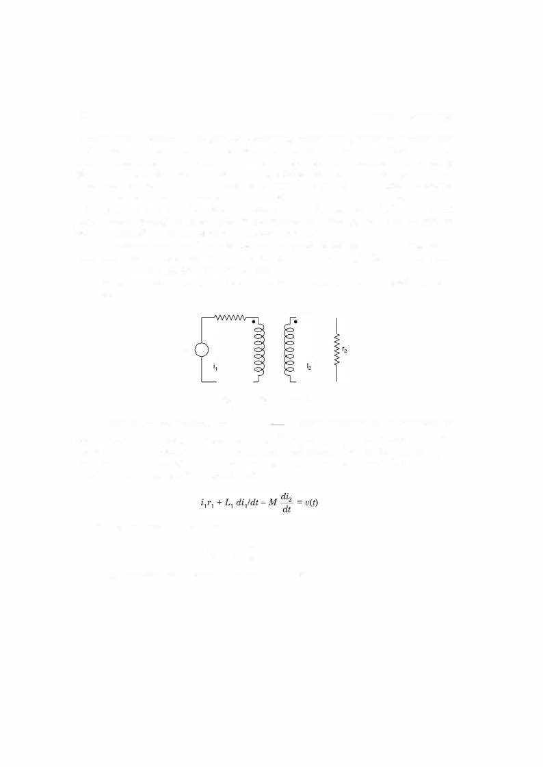
Suppose we are required to write loop equations for a mutually coupled circuit shown in |
|||||||
Fig. 1.29. |
|
|
|
|
|
|
|||
|
|
|
|
Fig. 1 .29. Coupled circuit. |
|||||
|
|
For primary loop the drops are |
i1r1 |
+ |
L1 |
dii |
+ drop in primary loop due to current in |
||
|
|
|
|
|
|
dt |
|
||
secondary loop. The voltage induced in primary will be determined by the direction of i2 with
respect to its dot in secondary loop. Since current is going away from the dot, the polarity of voltage on the primary side will be positive at the undotted terminal. Therefore, for current i1 it will be rise in voltage and the equation will be
and for the secondary loop, similarly
i.2r2 + L2 dti2 _ Mdti1 -0
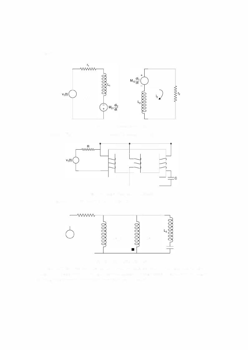
The equivalent two loops are as shown in Fig. 1.30.
A-C CIRCUITS |
1 03 |
The above example explains clearly how voltage sources (corresponding to induced voltages) are inserted in the coils which are magnetically coupled and the dots have been assigned.
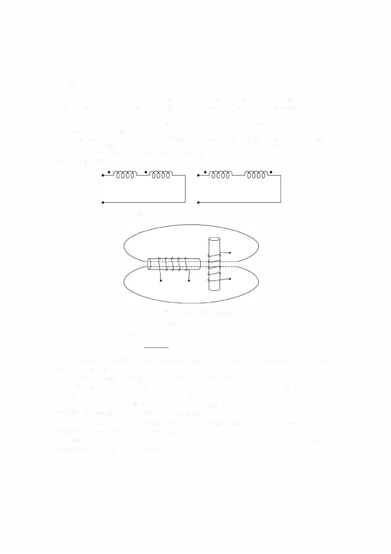
When the two coils are to be interconnected it is important to know whether the mutual inductance M is aiding or opposing. However, it is known that the effect on each of the two coils must be the same. Refer to Fig. 1.34(a) where the mutual inductance is aiding their self inductances whereas in (b) it is opposing. If L1 and L2 are the selfinductances ofthe two coils and M the mutual inductance, the total inductance say if is LA in case of Fig. 1.32(a) and LB that in Fig. 1.32(b) then,
Fig. 1 .34. (a) Two coils aid and (b) Oppose.
Fig. 1 .35. The coils at right angles.
|
LA |
A - |
|
+ |
|
|
and |
LB |
Ll + L2 |
- |
2M |
||
|
M== |
|
|
|
|
|
|
L |
|
L |
|
||
Therefore, |
|
4 |
|
B |
|
|
|
|
|
|
|||
This method provides a very convenient way of determining the value of mutual induct ance between the coils.
The co-efficient of coupling and the mutual inductance between the two coils shown in Fig. 1.33 are both zero. Although the flux of one coil appears to pass through the other coil, it does not actually link the turns of the other coil.
Therefore, the linkages are zero and the value of M is zero. It is only when one coil is rotated with respect to other that a linking occurs.
Example 1.27. Determine the inductance of the individual winding and the equivalent inductance when mutual inductance is 8H.
Since the flux through the two coils opposes each other, the mutual inductance is subtractive from each coil and hence