Basic_Electrical_Engineering_4th_edition
.pdf
THREE-PHASE INDUCTION MOTORS |
305 |
The slip ringrotororthe woundrotorcarries apolyphase windingsimilarto andwoundfor the same number of poles as the stator. The terminals of the rotor winding are connected to insulatedslipringsmountedonthe shaft. Carbonbrushes, bearing on theserings make the rotor terminals available external to the motor. The terminals of the rotor winding are brought out through slip ring to a suitably controlled and balanced rheostat.
8.3PRINCIPLE OF OPERATION
When a 3-phase supply is connected to the stator terminals (normally delta connected as perthe same voltage thetorque developedis higher as compared towhenit is star connected as
Fig. 8.1 . Schematic diagram of squirrel cage motor.
voltage per phase is line voltage in delta connection) ofthe squirrel cage motor, the currents in the statorwinding give rise to a constant magnitude rotating magnetic field which induces volt age in the stationary rotor conductors which is short circuited and hence circulates currents in the rotor conductors which produces certain flux and the interaction of stator and rotor fluxes giverise to torque and the rotor starts rotatinginthe directionofthe magnetic field due to stator winding. Initially the frequency of voltages induced in rotor conductors corresponds to supply frequency and as the relative speed between the stator magnetic field and rotor decreases the frequencyofthe voltageinduced inrotor also decreases. Under no loadconditionthe rotor tries to catch up with the stator magnetic field but it can't run at the same speed as the stator magnetic field as otherwise the relative speed will be zero and no voltage would be induced in the rotor conductors and hence no torque willbe developedinthe rotor. Therefore, the rotor always rotates at a speed less than the synchronous speed ofthe rotating stator magnetic field. As the motor is loaded the slip between the stator magnetic field and rotor increases. Under no load condition since the rotor has to meet its copper and iron losses only, the slip between the rotor and stator magnetic field is around 1% and as the motor is loaded the slip increases i.e. the speed ofthe rotor decreases. Theactionis similartodeshuntmotor.Thefullloadslipisnormally 5%. The slipis definedas
...(8.1)
where s is the slip, ns the synchronous speed ofthe stator rotating magnetic field, nr the actual speed ofthe rotor. The rotor moves in the same direction as the stator field because accordingto Lenz's law the rotor should move in a direction such that the emf induced in its conductors (or currentflowthroughits conductors) decreaseswhichis possible only ifthe relative speed between the rotor and the stator magnetic field decreases which means the rotor must rotate in the same direction as the statormagnetic field.

306 |
ELECTRICAL ENGINEERING |
The starting torque of an ordinary (the other one is double cage) squirrel cage motor is limited to approximately double the full load torque when full voltage is applied to the stator winding and under these conditions the starting current is five to eight times its full load value. It, therefore, follows thatin cases where high startingtorqueis required a differenttype ofrotor is necessary. In fact we will see that a double cage rotor or slip ring induction motor with rotor resistances provides high starting torque without drawinglarge starting current.
In bothtypes ofinductionmotors described the stator carriesthe primarywinding andthe rotor the secondary. There maybe situations whenitis desirable to have the primary onthe rotor and the secondary on the stator e.g. ifthe line voltage is high and the secondary current large it would he inconvenient to conduct large current to the rheostat through slip rings. In such a case, the primary wound on the rotor can be supplied with its relatively small current through slip rings, while the stationary secondary terminals can be connected directly to the rheostat. In either case, the revolving magnetic field will travel at synchronous speed with respect to the primarywinding. Inthefirstcase, itwillmove at synchronous speedin space, sincetheprimaryitself is stationary; inthe second case, it will movein space at a speed correspondingto slip frequency.
The number ofrotor slots should not be equal to stator, for ifthey were, the reluctance of the magnetic circuit wouldvary from maximum when teeth are opposite slots to minimum when teeth are opposite teeth. Such a pulsation would resultin additional core losses and infact more important is that the rotor would tend to lock with the stator especially at starting with teeth opposite teeth. This canbe avoidedby makingthe number ofstator and rotor teethprime to each other, therebyproviding a sort ofvernier actionbetweenthe two sets ofteeth.
It is desirableto build the statorlaminations so thatthe teeth and slots are parallelto the axis ofthe shaft but in the case ofthe rotor the laminations are slightly skewed to eliminate the locking action which is most pronounced ifthe air gap flux is radially disposed along the whole length ofthe oppositeteeth, the skewingintroduces atangentialcomponentinto the pull between opposite teeth and so tends to minimise locking action.
The air gap or more accurately the gap between the stator and rotor teeth should be as small as possible so as to have perfect coupling between the stator and rotor magnetic field and thus reducing the leakage fluxbetween the stator (primary) and rotor (secondary) winding. This is desirable as the secondary(rotor)currentuponwhichthe torque and power developed depend is supplied inductively from the primary the stator winding and hence good couplingbetween the two windings is essential. From this point ofview the induction motor has similar properties as the transformer and any air gap, however small, will cause the leakage reactance and the mag netising current to be greater than in an equivalent stationary transformer having a closed magnetic circuit. The effect ofthe air gap is to reduce the p.f. especially at light loads. The length ofair gap is, therefore, determined mainlyby mechanical consideration to avoidvibrationofthe shaft and wearing of the bearings and this may be smaller in low speed than in high speed machines.
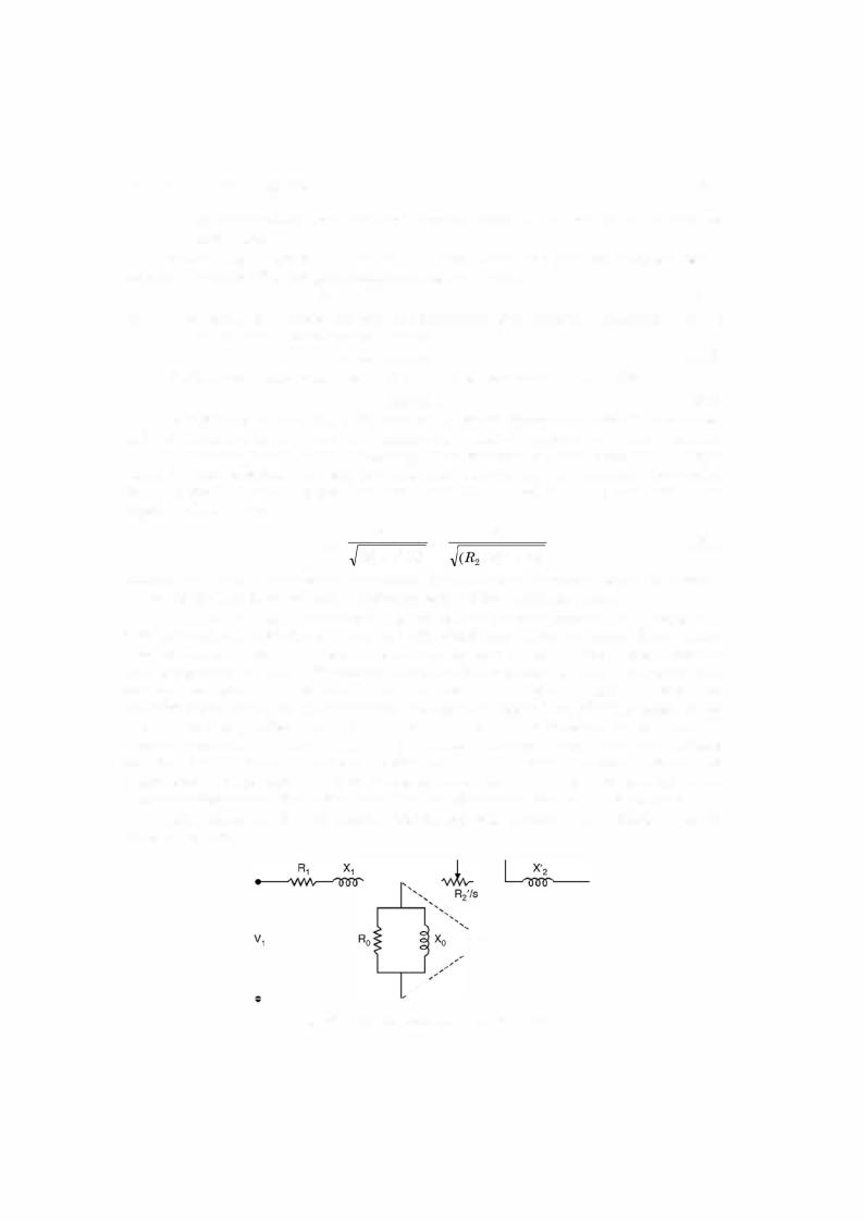
8.4EMF AND CURRENT RELATIONS (EQUIVALENT CIRCUIT)
In order to simplify the analysis the assumptions made are
(i)that the voltage V1 appliedf1; across each phase of primary is purely sinusoidal and alternating at frequency
(ii)that the fluxperpole is sinusoidally distributed in space around the air gap andthat it is rotating at synchronous speed and