Basic_Electrical_Engineering_4th_edition
.pdf374 |
ELECTRICAL ENGINEERING |
Construction ofHRC fuse
The HRC fuse consists of a ceramic body usually of steatite, pure silver element, clean silica quartz, asbestos washers, porcelain plugs, brass endcaps and copper tags (see Fig. 11.7). The brass end-caps and copper tags are electro-tinned. The metal end-caps are screwed to the ceramic body by means ofspecial forged screws to withstand the pressure developed under short
Fuse element
Contact blade
Fig. 11.7 H RC fuse link.
circuit condition. The contacts are welded to the end-caps. The assembly also includes solder of various types, cement and indicator devices. Deterioration ofthe fuse must involve a change in one or more ofthese meterials or a change in their structure. Normally the fuse element has two or more sectionsjoined by means ofa tinjoint. The fuse wire is not in the form ofa long cylindri cal wire as after it melts, it will form a string ofdroplets and will result into an arc between the droplets. Afterwards these droplets will also evaporate and a long arc will be struck. The purpose ofthe tinjoint is to limit the temperature offuse under small overload conditions. The melting point ofsilver is 960°C while that ofpure tin is 230°C. As the circuit is overloaded the melting of tin prevents the silver element from attaining high temperature. The shape ofthe fuse element depends upon the time-current characteristic required.
Fuse operation
When an HRC fuse operates, the element absorbs energy from the circuit and heats until it melts. The heat produced during operation is given by J i2Rdt where R is the instantaneous
resistance and i the instantaneous current during the operating time. The fuse element melts before the fault current reaches its peakvalue. As the element melts, it vaporizes and disperses. This action is then followed by a period of arcing during which chemical reaction between the silver vapour and the quartz powder takes place, which further results into building up a high resistance and reduces the current to zero. Thus the arc is quenched. Generally, the filling pow der used is quartz-sand as it can absorb heat at averyhigh rate and it does not evolve appreciable amount ofgas.
Cut-off Current
When an HRC fuse interrupts a heavyfault it exhibits an ability to limit the short circuit current. This ability is referred to as a 'cut off as shown in Fig. 11.8 and has the effect ofreducing the magnetic and thermal stresses both in the system and within the fuse itself under fault conditions. Cut-offis in fact one ofthe main reasons why HRC fuse is so successful as a protective device and it is at times preferred over the circuit breaker oflow ratings. Due to this property of


376 |
ELECTRICAL ENGINEERING |
sealing of the silver element within the fuse body with the help of special cementing and the soldering ofthe end caps. It has been found that HRC fuses maintain non-deterioration property unimpaired even after approximately 20 years oftheir manufacture.
(iv) Low-temperature operation. This is required to eliminate the deterioration ofthe fuses and to prevent overheating ofassociated contacts. This is achieved by employing fabricated ele ments ofpure silver which are specially designed to give a low temperature rise when carrying their full-rated current.
By this characteristic is meant that an HRC fuse on a distri bution system will isolate the faulty section from the healthy section whenever a fault takes place. In case ofan HRC fuse it is found that the time ofoperation is inversely proportional to the prospective short circuit current over a much wider range offault condition and, within practical limits, while the values of prospective short circuit current increase, the time of operation will continue to decrease without reaching a definite minimum. This means that a fuse oflow current rating will blow before a fuse of a higher rating, no matter how heavy the fault. It is, therefore, desirable while designingthe installationfrom the view point ofdiscrimination to use fuses ofthe same design and characteristics throughout, which will ensure that time-current characteristics of each succeeding current size will not cross and the characteristics will be parallel to one another upto the maximum values offault current.
Whenever an inductive circuit is interrupted, there is like lihood oflarge voltages induced. The magnitude ofsuch voltages depend upon the magnitude of the short circuit to be interrupted and the circuit constants. A careful design of the HRC fuse controls these over voltages and keeps them within safe limits.
Low cost. It is known that because ofthe cut-off characteristics of the HRC fuse, for the same rupturing capacity the actual current to be interrupted by an HRC fuse is much less as compared to any other interrupting device and hence it is less expensive as compared to other interrupting devices. It is, therefore, usual to employ a circuit breaker oflow rupturing capacity backed up by an HRC fuse where circuit breakers are necessary for other reasons. A combination of these two circuit interrupting devices works as follows. Whenever there is an overload the CB trips whereas for short circuits the HRC fuse operates.
Applications ofHRC Fuses
The applications ofHRC fuses are enormous but a few very important are: (i) protection of cables, (ii) protection ofbus bars, (iii) protection of industrial distribution system, (iv) contactor gear for motor control, (v) earth faults-both of low and high magnitude, (vi) semi-conductor rectifiers and (vii) aircraft.
It is to be noted that the HRC fuses cover a very wide range ofapplications. This involves the principles offuse design in varying degrees. For special application, the parameters ofthe fuse are defined to close limits. The design of HRC fuses for the same rupturing capacities for protecting an SCR are different from the one for protecting cables.
An HRC fuse rated for 150 amps continuous rating and 200 kArupturing capacity at 400 V used for protecting a semi-conductor device weighs about 30 gm whereas an industrial applica tion HRC fuse rated for 100 amps and 250 kA rupturing capacity weighs about 200 gms. The HRC fuses have been used for protecting aircraft equipments and offer many advantages not available by alternative means.


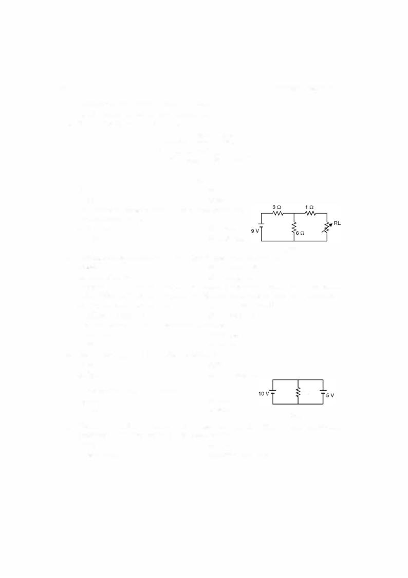
 PROBLEMS