Basic_Electrical_Engineering_4th_edition
.pdf

326 |
ELECTRICAL ENGINEERING |
this follows spinning where a continuous yarn ofsufficient strength is produced which is wound onbobbins. The process ofweavingconsists ofjoiningtwo sets ofthreads, one extends throughout the length ofthe fabric and the other one has its threads going across. This process is carried out in a loom. The process offinishing consists ofbleaching, dyeing, printing, and packing.
Loom motors require high starting torque, frequent starting and stopping and low tem peratureriseunderfull loadcondition. Therefore, totallyenclosedfancooled, hightorquesquirrel cage induction motors are used.
Spinning motors require moderate startingtorque andsmooth acceleration, so as to have straight and unbroken yarns. Normally a 4 or 6 pole squirrel cage induction motor is used.
Cementmills. The raw material required consist oflimestone, silica, alumina andferric oxide. The lime stone is crushed and a required amount of iron ore is added and then they are grounded in a grinding mill. The powder from this grinding mill is homogenised in silos, by passage ofair from bottom through the medium and is then fed into the kiln, from where cement clinker at hightemperature is obtained. This clinker is then air cooled in special type ofcoolers. The motors usedforcrushers is the slip ringinduction motorhaving 200 to 250% pullout torque.
Coal mining.For drilling incoal mines, usuallyinductionmotors withflame proofenclo sures are used. Sometimes highfrequency (150 to 200 Hz) motors are used. This is done toreduce the size ofthe motor for the same power ratings. For raising coal or raising or lowering men and some equipments usually wound rotorinductionmotor is used. While applying brakes, initially d.c. rheostatic braking is used but finally for dead stops, mechanical brakes are used. For large size mines, usually d.c. motor with Ward-Leonard Ilgner system is employed for mine winders.
Lifts. For lifts normally slip ring induction motors having high starting torque, high overload capacity and pull outtorques, are used.
Lathe,grindingandmillingmachine.Herethe machinetools require constant operating speed and low starting torque and therefore, d.c. shunt motors or squirrel cage motors are usually used.
Cranes. For cranes or hoist, the requirements are high starting torque and frequent switching operations. For this d.c. series motor is used. In case ofa.c. supply, slip ring induction motors are used where speed controlis obtained by rotor resistance.
Atypicalbut undesirable operation ofa 3-phase inductionmotoriswhatis knownas single phasing operation ofa 3-phaseinduction motor. Suppose a three-phaseinduction motor is operat ingunder normal condition ofsupply and suddenly one ofthe three phases ofthe lines blows off. The machine is put on the remainingtwo phases. This is known as single-phasing operation ofa 3-phase induction motor. The machine continues to run but at a slightly reduced.J3 speed. Ahum-
ming noise from the machine is heard. The current in the line becomes times its normal
value. It is not the quantityofcurrent that is dangerousforthe operationofthe motorto continue but the quality ofcurrent which may overheat the stampings of the rotor which may behave a short-circuited secondary and the stator may draw large current resulting in complete damage of the motor. Therefore, moment humming noise is heard the supply shouldbe switched offfrom the motor.

THREE-PHASE INDUCTION MOTORS |
327 |
8.1. A delta connected 400 V, 30 hp, 750 rpm squirrel cage motor takes a full load current of37A and has a full load slip of 4.5 per cent. The impedance per phase is 3.9 ohms. Determine the starting torque and the starting current taken from the supply if the motor is started by
(a) Direct switching
|
(b) An auto-transformer starter with a 70% tapping |
|
|
|
|
|
|
|
|
|
|||||
8.2. |
(c) A star-delta starter. |
[Ans. (a) 291.6 Nm, 177 A (b) 143 Nm, 86.8 |
|
(c) 97 Nm, 59 A] |
|||||||||||
A 3-phase squirrel cage motor has maximum torque equal to twice full loadtorque R2' |
|
0.2 and |
|||||||||||||
|
X2' |
|
2 |
|
Determine the ratio of starting torque to full load torque, if it is started by |
|
(a) |
DOL |
|||||||
|
|
|
|
|
|
|
|
A |
|
|
|
|
|
||
|
starter (b) Star-delta starter (c) Auto-transformer starter with 70% tapping. |
|
|
|
|
|
n |
||||||||
|
|
|
|
n. |
|
[Ans. (a) 0.396 FLT (b) 0.132 FLT (c) 0.194 FLT.] |
|||||||||
8.3. Explain why the rotor of an induction motor rotates in the same direction as the stator magnetic |
|||||||||||||||
8.4. |
field and why the spe d of the motor is less than the synchronous speed. |
|
|
|
|
= |
|
|
|
|
|||||
Explain what you mean by single phasing operation of a 3-phase induction motor. |
|
|
|
|
|||||||||||
8.5. |
Comment on the statement |
|
|
|
|
|
|
|
|
|
|||||
|
(a) |
|
|
|
e |
|
|
|
|
|
|
|
|
|
|
|
The rotating fields due to stator and rotor are stationary with respect to each other. |
|
|
|
|||||||||||
8.6. |
= |
|
|
|
|
|
|
|
|
|
|
|
|
|
|
(b) Induction motor can be regarded as a generator feeding a fictitious resistance load. |
|
|
|
|
|||||||||||
A 4-pole induction motor is running at 1440 rpm from a 50 Hz supply. Find the percentage slip |
|||||||||||||||
8.7. |
and the frequency ofrotor current. |
|
|
|
[Ans. 4% 2 Hz] |
||||||||||
A 3-phase induction motor has |
4-pole star-connected stator winding and runs on a 220 V 50 Hz |
||||||||||||||
|
supply. The rotorresistance is 0.1 ohm and reactance 0.9 ohm. The ratio ofstator torotor turns is |
||||||||||||||
|
1.75. The full load slip is 5%. Determine for this load (a) the totaltorque (b) the horsepower. Also |
||||||||||||||
|
find (c) the maximum torque (d) the speed at maximum torque. |
|
|
|
|
|
|
|
|
|
|||||
8.8. |
|
|
|
|
|
[Ans. 4.28 kgm (b) 8.4 hp (c) 5.73 kgm (d) 1330 rpm_] |
|||||||||
A slip ring induction motor runs at 290 rpm on full load when connected to a 50 Hz supply. |
|||||||||||||||
|
Calculate (a) the number of poles (b) the slip (c) the slip for full load torque if the total resistance |
||||||||||||||
|
of the rotor circuit is doubled. |
[Ans. a |
) |
20 (b) 3.3% (c) 6.6%.] |
|||||||||||
8.9. |
|
|
|
|
|
( |
|
|
|
|
|
|
|
|
|
The power input to a 500 V, 50 Hz, 6 pole, 3-phase induction motor running at 975 rpm is 40 kW. |
|||||||||||||||
|
The stator losses are 1 kW and the friction windage losses total 2 kW. Determine |
(a) |
the slip |
||||||||||||
|
(b) the rotor copper loss (c) the brake horsepower (d) the efficiency. |
|
|
c |
|
|
|
(d) 90%.] |
|||||||
|
|
|
|
|
|
[Ans. (a |
|
|
|
|
|
||||
|
|
|
|
|
|
) 0.025 (b) 975 W ( |
) 48.4 hp |
|
|
|
|
||||

SINGLE PHASE INDUCTION MOTORS |
329 |
Aninductionmotorwitha cagerotor and singlephase statorwindingis shownschematically in Fig. 9.1. The actual stator winding as mentionedearlier is distributed in slots so as to produce an approximately sinusoidal space distributionofmmf.
9.2PRINCIPLE OF OPERATION
Suppose therotoris at rest and 1-phase supplyis givento stator winding. The currentflowingin the stator winding gives riseto anmmfwhose axis is alongthe windinganditis a pulsating mmf, stationary in space and varying in magnitude, as a function oftime, varyingfrom positive maxi mum to zerotonegative maximum andthis pulsating mmfinducescurrentsin the short-circuited rotor of the motor which gives rise to an mmf. The currents in the rotor are induced due to transformer action and the directionofthe currents is such that the mmfso developed opposes the stator mmf. The axis of the rotor mmf is same as that of the stator mmf. Since the torque developedis proportional to sine ofthe angle betweenthe two mmfand since the angle is zero, the net torque acting on the rotor is zero and hence the rotor remains stationary.
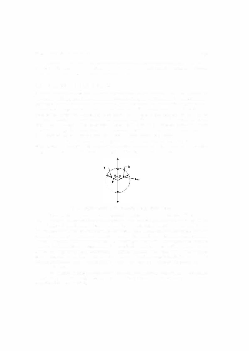
For analytical purposes a pulsating field can be resolved into two revolving fields ofcon stant magnitude and rotating in opposite directions as shown in Fig. 9.2 and each field has a magnitude equal to half the maximum length ofthe original pulsating phasor.
II\I'\\ (()
''.........
Fig. 9.2. Representation of the pulsating field by space phasors.
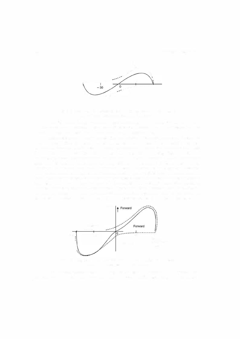
These component waves rotate in opposite direction at synchronous speed. The forward (anticlockwise) and backward-rotating (clockwise) mmfwaves fand b are shown in Fig. 9.2. In case of3-phaseinduction motor there isonlyone forwardrntating magneticfieldandhencetorque is developed and the motor is self-starting. However, in single phase induction motor eachofthese component mmf waves produces induction motor action but the corresponding torques are in opposite direction. Withthe rotor at rest theforward and backward field produce equal torques butopposite in direction andhence no nettorqueisdevelopedonthemotor and the motorremains stationary. Iftheforward andbackward air gap fields remained equal whenthe rotorisrevolving, each of the component fields would produce a torque-speed characteristic similar to that of a polyphase induction motor with negligible leakage impedance as shown by the dashed curves f and b in Fig. 9.3.
The resultant torque-speedcharacteristic whichis the algebraic sumofthe two component curves shows thatifthe motor were startedby auxiliary means it would produce torque in what ever direction it was started.

SINGLE PHASE INDUCTION MOTORS |
331 |
amplitude revolving fieldinthe air gap ofa balanced polyphase motor. Therefore, in the normal running range of the motor, the torque-speed characteristic of a single phase motor is not very much differentfromthatofapolyphase motorhavingthe same rotor andoperatingwiththe same maximum air gap flux density.
In addition to the torque shown in Fig. 9.4, double-stator frequency torque pulsation are produced bythe interaction ofthe oppositelyrotatingflux and mmfwaves which move past each other at twice synchronous speed. These doublefrequencytorques produce no average torque as these pulsations are sinusoidal and overthe complete cycle the average torque is zero. However, sometimes these areadditiveto the maintorque andforanotherhalfa cyclethese are subtractive and therefore a variable torque acts on the shaft ofthe motor which makes the motor noisier as compared to a polyphase induction motor where the total torque is constant. Such torque pulsa
tions are unavoidable insingle phase circuitsTa . Mathematically
F
Let |
TI= I |
sin mt |
|
|
|||
|
|
2 |
sin |
|
mt |
|
|
|
|
(1 - cos mt) |
...(9.2) |
||||
|
= m |
|
|
2 |
2 |
||
|
= KIm |
|
|
|
|
|
|
KIm2
So the expression for torque contains a constant term superimposed over by a pulsating torque with pulsation frequency twice the supplyfrequency.
9.3STARTING OF SINGLE PHASE INDUCTION MOTORS
The single phase induction motors are classified based on the method ofstarting method and in factare knownbythesamename descriptive ofthemethod.Appropriate selection ofthese motors depends upon the starting and running torque requirements of the load, the duty cycle and limitations on starting and running current drawn from the supply by these motors. The cost of single phase induction motor increases with the size ofthe motor andwith the performance such as startingtorque to current ratio (higher ratio is desirable), hence, the user will like to go in for a smaller size (hp) motor with minimum cost, ofcourse, meeting all the operational requirements. However, if a very large no. offractional horsepower motors are required, a specific design can always be worked out which might give minimum cost for a given performance requirements. Following are the starting methods.
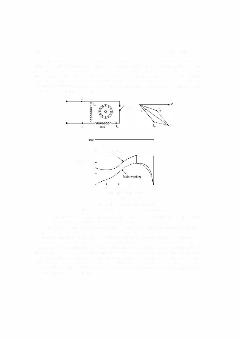
(a) Split-phase induction motor. The stator of a split phase induction motor has two windings, the main winding and the auxiliary winding. These windings are displacedin space by 90 electrical degrees as shown in Fig. 9.5 (a). The auxiliary winding is made ofthin wire (super enamel copper wire) so that it has a highRIXratio as compared to the main winding which has
thick super enamel copper wire. Since the two windings are connected across the supply the |
||||||
current |
Im |
and |
Ia |
|
Ia |
|
|
|
in the main winding and auxiliary winding lag behind the supplyvoltage V, Ia |
||||
|
|
|
|
= Im |
|
Im |
leading the current |
Fig. 9.5(b). This means the current through auxiliary winding reaches |
|||||
maximumvalue first and the mmforflux due to lies alongthe axisofthe auxiliarywinding and
Im
after some time (t 9/w) the current reaches maximum value andthe mmforflux due to lies
alongthemainwindingaxis. Thusthemotorbecomes a 2-phaseunbalancedmotor. Itisunbalanced since the two currents are not exactly 90 degrees apart. Because ofthese two fields a starting
332 |
ELECTRICAL ENGINEERING |
torque is developed and the motor becomes a self-starting motor. After the motor starts, the auxiliary windingis disconnected usually by means ofcentrifugal switch that operates at about 75 per cent ofsynchronous speed. Finally the motorruns because ofthe main winding. Since this being single phase some level of humming noise is always associated with the motor during running. A typical torque speed characteristic is shown in Fig. 9.5 (c). It is to be noted that the direction ofrotation ofthe motor canbe reversed by reversing the connection to either the main winding or the auxiliary windings.
H |
|
|
|
|
Switch |
|
|
|
|
|
|
|
|
|
|
supply |
Main |
|
|
|
|
|
|
v |
|
|
|
|
|
|
|
|
|
|
(a) |
|
|
|
(b) |
|
|
|
|
|
|
|
|
|
|
300 |
Main and |
|
|
|
|
|
|
|
auxiliary winding |
|
|
||
|
Percent |
200 |
|
|
|
|
|
|
of torque |
|
|
|
|
|
|
|
|
1 00 |
|
|
|
|
|
|
|
0 |
20 |
40 |
60 |
80 |
1 00 |
|
|
|
Percent |
synchronous speed |
|
||
(c)
(b)Phasor diagram at starting (c) Typical torque-speed characteristic.
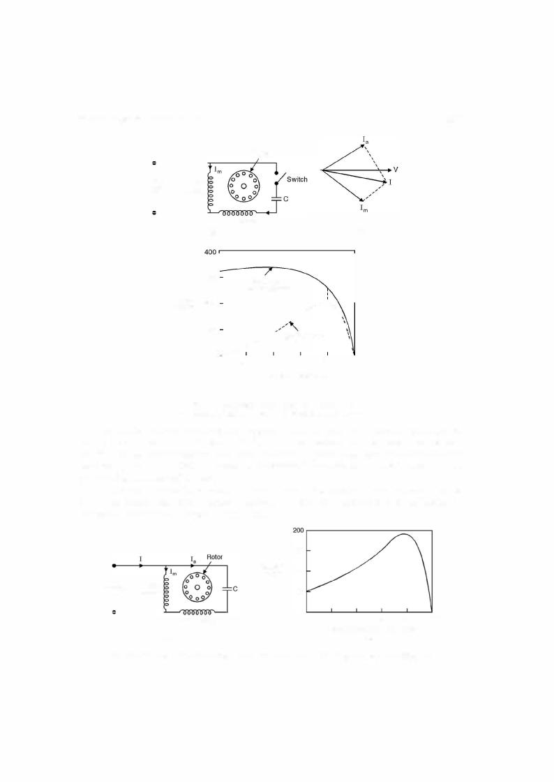
(b)Capacitor start induction motor. Capacitors are used to improve the starting and running performance ofthesingle phase inductions motors.Fig. 9.5. Split phase induction motor (a) Connection
The capacitor start induction motor is also a split phase motor. The capacitor of suitable value is connected in series with the auxiliary coil through a switch such that Ia the current in the auxiliary coil leads the current Im in the main coil by 90 electrical degrees in time phase so that the starting torque is maximum for certain values ofIa and Im. This becomes a balanced 2- phase motor if the magnitude of Ia and Im are equal and are displaced in time phase by 90° electrical degrees. Since the twowindings aredisplacedin space by 90 electrical degrees as shown in Fig. 9.6 maximum torque is developed at start. However, the auxiliary winding and capacitor are disconnected after the motor has picked up 75 per cent ofthe synchronous speed. The motor will start without any humming noise. However, after the auxiliary winding is disconnected, there will be some humming noise.