Basic_Electrical_Engineering_4th_edition
.pdf

DC MACHINES |
269 |
Armature copper losszat any load current Ia2 Ra, v
Field copper loss = -
Rr,
Total loss at load = Mechanical andironlosses+Armaturecopperloss+ FieldCopperloss + Stray Loss
Swinburnetestcanthusbeutilisedtoobtainefficiencyofthe machine at differentloadings. However, the test does notprovide anyinformationregardingthe temperaturerise ofthe windings ofthe machine.
Example 6.11. Swinburne test gave the following results on a de shunt motor:
Supply voltage 500 V, no load current 5A, Armature resistance 0.5.Qand Field resistance 250 .D. Determine the efficiency ofthe machine (i) as a generator delivering 100A at 500 V(ii) as a motor having a line current of 100 A at 500 V Neglect temperature rise during operation. Assume stray losses at 1 % of output.
Solution. Input at no load
500 x 5 = 2500 watts
Field current |
|
I = |
500 |
= 2 A |
|
|
|
|
|
|
250 |
|
|
|
|
Hence armature current |
5 |
- 2I= 3 A= 22 x 250 = 1000 watts |
|||||
Field copper loss |
|
||||||
Armaturecopper loss |
|
|
= 32 x 0.5 = 4.5 watts |
||||
Mechanical and iron loss |
|
|
|
2500 - 1000 - 4.5 |
|||
|
|
|
= 1495.5 watts |
||||
(z) Working as a generator |
|
= |
500 x 100 |
|
|
||
Output power |
|
|
|
|
50,000 watts |
||
Armature current |
|
100 + 2 = 102 A |
|
|
|||
Armaturecopperloss |
|
|
= 1022 x 0.5 = 5202 watt |
||||
|
|
= |
1 |
|
= |
||
|
Stray loss = |
x 50,000 = 500 watts |
|||||
|
500 x 100 = |
-- |
|
|
|
||
|
|
|
|
100 |
|
|
|
Total losses = 5202 + 1000 + 1495.5 + 500 |
|||||||
|
|
|
= 8197.5 watts |
||||
|
|
. . |
|
50000 |
|
|
|
Hence efficiency = 58197.5 = 0 |
.86 or 860Yo Ans. |
||||||
(iz) Working as a motor |
|
|
|
|
|
|
|
Input to the motor |
|
|
|
50,000 watts |
|||
Armature current |
|
100 - 2 = 98 A |
|
|
|
||
Armaturecopper loss |
|
|
= 982 x 0.5 = 4802 watts |
||||
Output = 50,000 - 4802 - 1000 - 1495.5 = 42702.5 watts
Stray loss = 427 watts

270 |
|
ELECTRICAL ENGINEERING |
Hence net output = 42702.5 |
- 427 = 42275.5 watts |
|
. . |
42275.5 |
|
Hence efficiency = |
50,000 |
x 100 = 84.55% Ans. |
Example 6.12. A 100 KW belt driven shunt generator running at 300 rpm on 220 V bus bars continues to run as a motor when the belt breaks then taking 10 KW. Determine its speed. Assume armature resistance 0.025 D, field resistance 60 Q contact drop under each brush 1 V. Ignore armature reaction.
Solution. Current taken bv the motor lO,OOO220
Initially current delivered bythe generator 455 A Hence the induced emf 220 + 455 x 0.025 = 231.375
The back emfwhile motoring 220 - 45.5 x 0.025 = 218.87 V
Add 2 volts contact drop in case ofgenerator and subtract 2 volts in case ofmotor, we have |
||||||
Total induced emffor generator 233.375 and for the motor back emf216.87 |
||||||
Hence the speed under motoring• |
condition |
|
|
|||
216·87 |
x 300 |
= |
279 ·p |
m |
Ans. |
|
233.375 |
|
|
r |
|
||
Example 6.13. A series generator, having an external characteristic which is a straight line through zero to 50 V at 200 A, is connected as a booster between a station bus bar and a feeder of 0.3 Q resistance. Determine the voltage between the far end of the feeder and the bus bar at a current of (a) 1 60 A (b) 50 A.
Solution. (a) Since the generator characteristic is a straight line passing through the origin, at 160 A the bus bar voltage willbe
20050 x 160 = 40 volts
and the drop in the feeder due to the flow of 160 Ais 160 x 0.3 = 48 volts
and hence the difference ofvolts between the bus bar and the far end ofthe feeder is 48 - 40 = 8 volts Ans.
(b) Similarly for 50 A, the bus bar voltage is
50
200
andthe drop inthe feeder due to 50A current flowis 50 x 0.3 = 15 volt
and hence the difference in voltage is
15 - 12.5 = 2.5 V Ans.
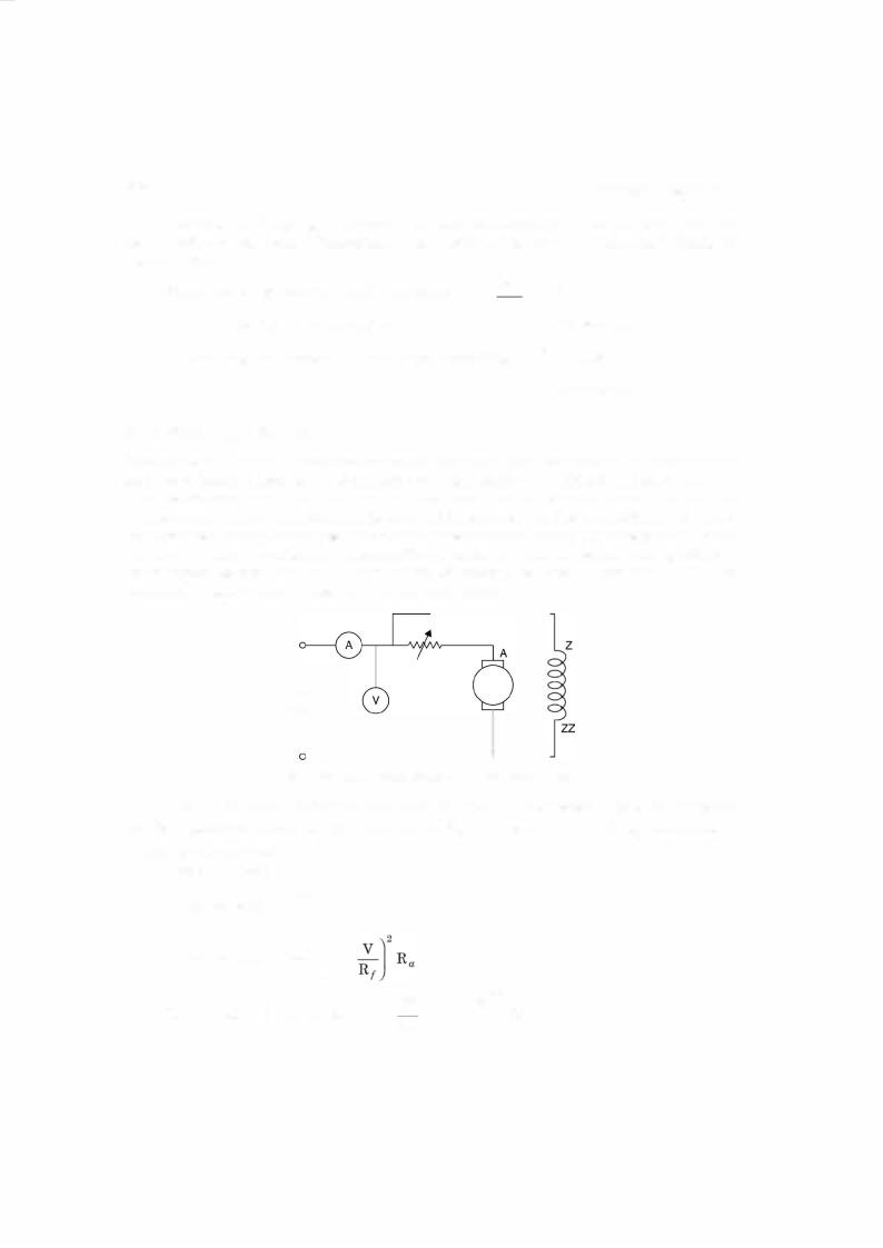
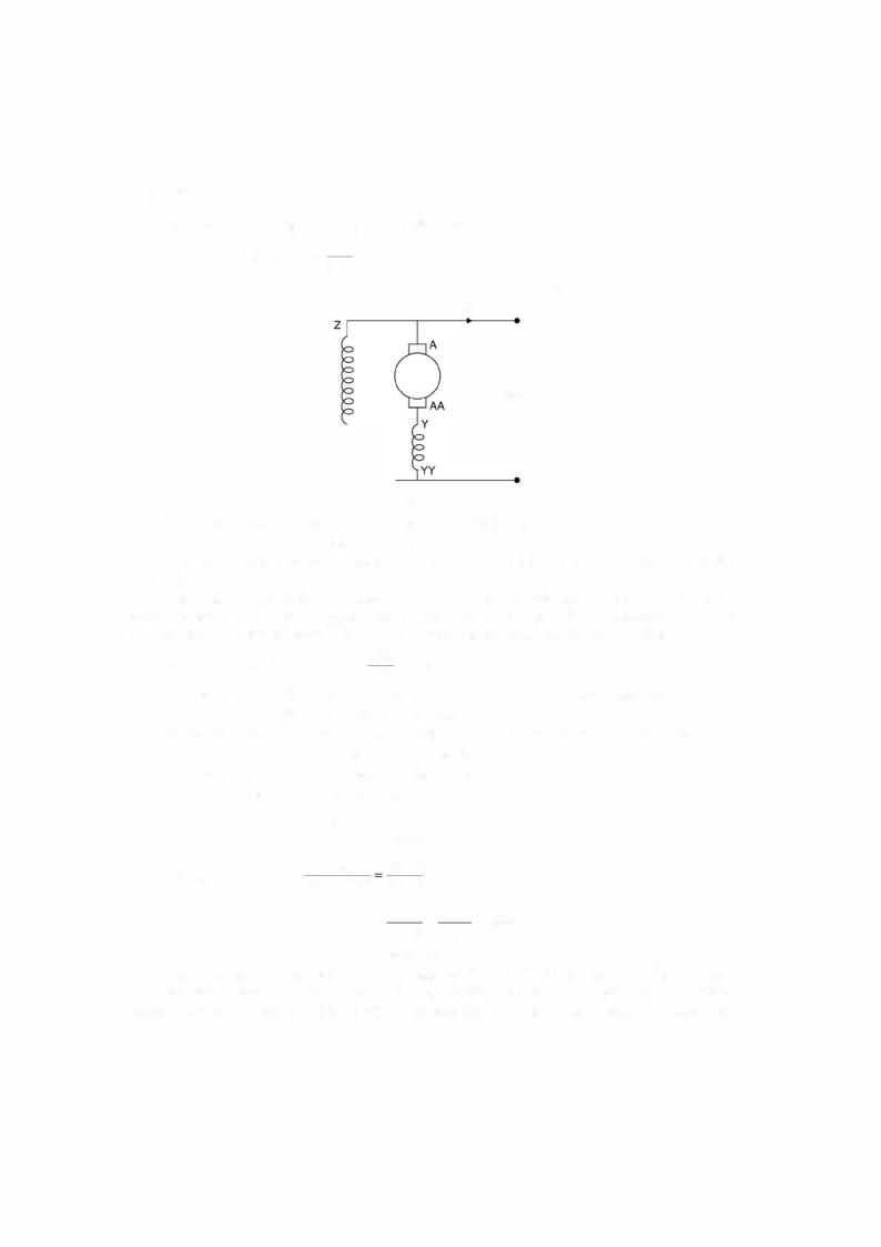
Example 6.14. A long shunt compound generator delivers a load current of 50 A at 500 V and has armature, series field and shunt field resistances of 0.05 !1, 0.03 Q and 250 Q respec tively. Determine the induced emf and the armature current. Allow 1 volt per brush for contact drop.
DC MACHINES |
|
|
|
|
|
|
271 |
Solution. The long shunt figure is given here |
|
|
|||||
The shunt field current |
5oo |
= 2 A |
|
|
|
|
|
Hence armature current |
250 |
= I + |
]sh |
= 50 |
+ 2 = 52 A |
|
|
Ia |
Ans |
. |
|||||
L |
|
|
|
||||
|
|
|
|
|
50 A |
|
|
500 v
zz
|
|
|
|
|
|
Fig. E6.14 |
|
|
|
|
|
|
The drop in the armature and the series field resistance |
|
|
|
|
||||||||
|
52(0.05 |
|
|
0.03) = 4.16 |
|
|
|
|
|
|||
The brush drop 2 volts. Hence the e.m.f. induced is 500 + 2 + 4.16 = |
|
|
||||||||||
volts. Ans. |
|
|
|
+ |
|
|
|
|
|
506.16 '.:::'506..2 |
||
Example 6.15. A 250 Vshunt motor on no load runs at 1000 rpm and takes 5A. The total |
||||||||||||
armature and shunt field resistances are respectively 0.2 .Q and 250 |
|
Determine the speed |
||||||||||
when loaded taking a current of 50A, if armature reaction weahens the field by |
|
|||||||||||
Solution. The field current is |
|
250 = 1 A |
|
|
.Q. |
|
|
3%. |
||||
|
|
250 |
|
|
|
|
|
|||||
Under no load condition the armature current is 5 - 1 = 4 A. Hence back emfis |
||||||||||||
|
250 - 4 x 0.2 |
|
|
|
249.2 volts |
|
|
|
|
|
||
Since the armature current is 4 A which is very small as compared to 50 A as far as |
||||||||||||
armature reaction effect inconcerned, hence we neglect the effect. |
|
|
|
|
||||||||
|
|
|
= |
|
|
|
|
|
|
|
|
|
The back emfwhen 50 A is drawn by the motor |
|
|
|
|
|
|||||||
Now |
250 - (50 - 1) x 0.2 = 240.2 volts |
|
|
|
|
|
||||||
249.2 =Kqi x 1000 |
|
|
|
|
|
|||||||
|
240.2 |
|
= |
|
0.97 KN |
|
|
|
|
|
|
|
Hence |
0.97 KNcp |
|
|
240.2 |
|
|
|
|
|
|
||
Kcp x 1000 |
|
249.2 |
|
|
|
|
|
|
||||
or |
N= |
|
240.2 x |
1000 |
- 993_7 |
|
|
|
|
|||
|
|
|
|
|
|
249.2 |
0.97 |
|
|
|
|
|
'.:::'994rpm. .
Example 6.16. A shunt generator delivers 50 KWat 250 Vand 400 rpm. The armature and field resistances are 0.02 .Q and 50 .Q respectively. Determine the speed of the machine running as a shunt motor and taking 50KWinput at 250 V Allow 1 Vper brush for contact drop.