Basic_Electrical_Engineering_4th_edition
.pdf


TRANSFORMER |
229 |
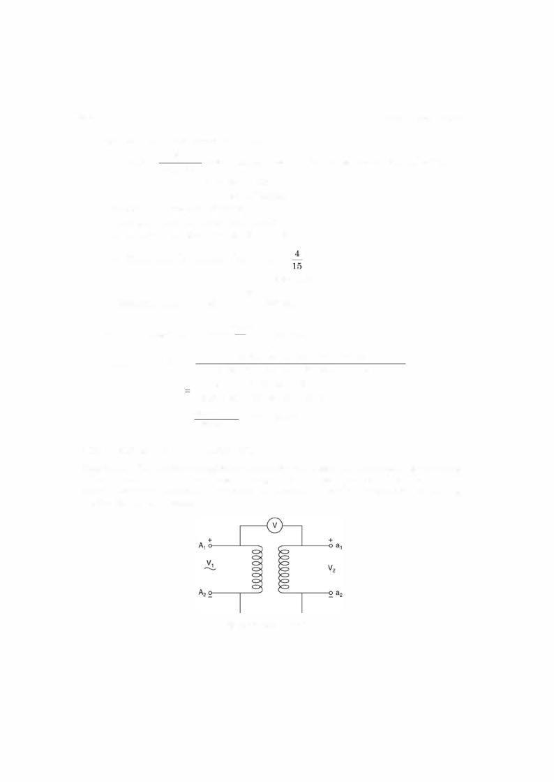
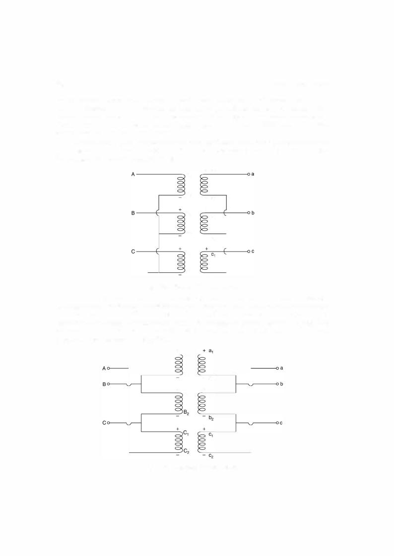
So, the phrase polarity of a transformer appears to be vague. What we are interested here is to know the instantaneous polarities of the terminals A1, Ai, a1 and a2 i.e. if at any instant oftime A1 is positive what are the polarities ofA2, a1 and a2. Sometimes even A1 A2, a1 and a2 are not marked on the body of the transformer. How to mark the polarities of the terminals. In case, the terminal marking is not there, we might arbitrarily mark these termi
nals and make connections as shown in Fig. 5.20. Suppose it is a step down transformer i.e. V1 |
|||
> V2 and if the voltmeter reads V = V1 - V2 the polarities of the four terminals will be as |
|||
indicated in Fig. 5.20. However, ifV = V1 V2 (Therefore, the range ofthe voltmeter should be |
|||
at least equal to (V1 + V2)) retaining the polarities ofA1 and A2 as in Fig. 5.20, the polarities of |
|||
a1 should be negative and that of a2 as+positive. The first type of connection is known as |
|||
subtractive polarity as V = |
V1 - V2 as shown in Fig. 5.20 and the other type is known as |
||
additive polarity as V = V1 |
V2. |
|
|
The knowledge ofpolarities of the transformer is very important whenever two or more |
|||
to be interconnected |
e.g. |
parallel operation of two or more trans |
|
than two transformers are + |
|
|
|
formers when one transformer is not sufficient to supply certain amount ofload or three single phase transformer to be connected as three phase transformers.
If the polarities of the two transformers to be connected in parallel are known it is easy to connect them in parallel as shown in Fig. 5.21.
++
+ |
+ |
Load |
|
|
Fig. 5.21 . Parallel connection of two transformers.
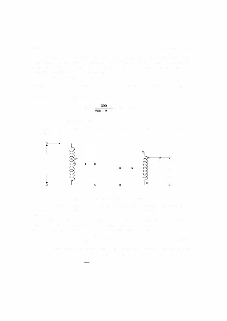
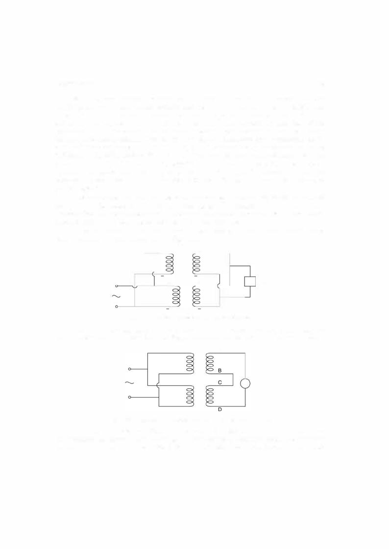
However, if the polarities are not known following procedure is used which again in volves knowledge of polarities. Refer to Fig. 5.22 connectAthe primaries in parallel arbitrarily
v
Fig. 5.22. Procedure for parallel connection of two transformers.
without caring for the polarities. Short two secondary winding terminals ofthe two transform ers arbitrarily as shown in Fig. 5.22 (B and C) and connect a voltmeter across the other two secondary terminals A and D as in Fig. 5.22. Ifthe voltmeter reads zero, remove the voltmeter
TRANSFORMER |
231 |
The relations between phase and line quantities (voltage and current) for star and delta connections have already been discussed in Chapter 3.
For transmission of power normally star/star transformers are used whereas for distri bution where single phase loads are also to be taken care of delta/star transformers are used.
5.1 3 TESTING OF TRANSFORMERS
Following tests are usually carried out on a transformers :
1.O.C. test or No load test
2.S.C. test
3.Direct loading of the transformer
4.Indirect loading or artificial loading or phantom loading or Sumpner's test.
The O.C. test and S.C. tests have already been discussed in detail. Direct loading is carriedoutforobtaining efficiency, regulation and temperature rise ofthe transformerwindings. Direct loading means the transformer is to be loaded to its rated capacity for specified number of hours to find out temperature rise. Hence, this method of testing is normally not recom mended especially for large capacity transformers as it involves huge amount of energy to be wasted only for testing of the transformer.
The indirect method or phantom loading method requires only iron and copper losses to be supplied corresponding to full load and still temperature rise corresponding to rated capac ity ofthe transformer can be obtained. The only drawbackis that it requires an additional and identical transformer for the transformer to be tested.
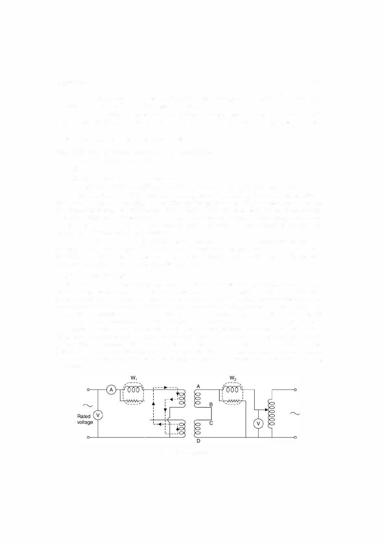
5.1 3.1 Sumpner's Test
Refer to Fig. 5.25. As mentioned, we need an additional identical transformer and the two transformers are connected in parallel (subtractive polarity) as shown in Fig. 5.25. Voltmeter
connected across |
|
should read zero. Once this condition is achieved a single phase variable |
||
lowvoltage sourceisconnected across |
Thevoltageis so adjusted thatratedcurrentcirculates |
|||
offered by the secondaries is only theAD. |
i.e. R1', X1' and R2 and |
|||
in the two |
secondarises of this transformer. The voltage required is low as the impedance |
|||
|
AD |
|
|
|
short circuit impedances in series
X2 in series. These secondary currents are reflected in the primary as shown by dotted line and these currents circulate in the primary windings only and these do not appear on the line side of the primary windings. The current in the two windings corresponds to rated current ; hence it is as though the transformer were fully loaded and, therefore, itis known as phantom loading. The current is circulated for a specified number of hours and temperature rise of the winding is recorded.
Low voltage
Fig. 5.25. Sumpner's test.