Basic_Electrical_Engineering_4th_edition
.pdf
DC MACHINES |
275 |
6.5.What things distinguish motor action from generator action in a de machine ?
6.6.Derive emfequation for a d.c. machine.
6.7.Derive an expression for the torque developed by a de motor.
6.8.Classify the de machine based on excitation systems.
6.9.Explain with a neat diagrams how you obtain magnetisation characteristic of a de machine and explain the significance ofthe characteristic.
6.10.vVhat is meant by self excitation of a de generator ? Discuss requirements for self-excitation.
6.11.Draw and discuss external (load) characteristics of (i) shunt (ii) series and (iii) compound de generators.
6.12.Derive mathematically torque-speed characteristic of various de motors. Draw the curves and discuss them.
6.13.Discuss various losses in a de machine.
6.14.A4-pole generatorhas a fluxof40 mWbperpole andalap connected armaturewith 740 conductors.
Determine the emf generated on open circuit at 1000 rpm. |
[Ans. 494 V] |
6.15.A 4Q-pole shuntQgenerator with lap connected armature having field and armature resistances of 50 and 0.1 respectively supplies sixty 100 V 40 watt lamps. Calculate the total armature
current, the current per armature path and the generated emf. Allow a contact drop of 2 volts.
[Ans. 26 A, 6.5 A 104.6 V] 6.16. A 4-pole, 500 V, shunt motor has 720 wave connected conductors on it's armature. The full load armaturecurrent is 60 A and the flux per pole 0.03 Wb. The armature resistance is 0.2 Q and the contact drop is 1 V per brush. Calculate the full load speed of the motor. [Ans. 675 rpm]
6.17.A 4-pole generator supplies a current of 143A. It has 492 armature conductors
(i)Wave connected
(ii)Lap connected. The brushes are given an actual shiftof 10°. When the generator is delivering full load. Determine the demagnetising ampere turns per pole. The field winding is shunt connected and takes lOA. Determine the no. ofextra shunt field turns necessary to neutralise
the demagnetisation. |
[Ans. (i) 1040, 104 turns (ii) 520, 52 turns.] |
6.18.A 500VQ shunt motor takes 4 A on noload. The armature resistance including that ofthe brushes is 0.2 and the fieldcurrent is 1 A. Determine the output and efficiencywhen the input current is
(i) 20 A (ii) 100 A. [Ans. (i) 10.75 h.p. 79.3%, (ii) 62.7 h.p. 92.1%]
6.19. A 480 V, 25 hp shunt motor took 2.5 A when running light. Taking armature resistance to be |
|
0.6 Q, field resistance 800 Q and brush drop 2 V, find the full load efficiency. |
[Ans_ 0.885] |
6.20.Describe with neat sketches the construction of armature, field magnet and commutator of a de machine.
6.21.Why are some parts of a de machine laminated and which parts are laminated ?
6.22.Explain the process of commutation in a de machine. What causes sparking on the commutator surface ? How can it be minimised.
6.23.Explain the conditions required for self excitation of a de generator.
6.24.Explain with neat diagram how you conduct Swinburne's test on a d.c. mechine. Whatinformation you gather from this test.
6.25.Derive speed torque characteristics of (a) d.c. shunt motor (b) d.c. series motor and discuss their application.
6.26.Derive speed current andtorque current characteristics of(a) d.c. shunt and (b) d.c. series motors.
6.27.Explain with the help ofneat sketches a three-point starter. Why a starter is required for starting a motor ?
6.28.A d.c. shunt motor is running at normal speed and suddenly it picks up very high speed. Give reason.


THREE-PHASE SYNCHRONOUS MACHINES |
277 |
current. Since the armaturewindingcarriesloadcurrent, it has tohandle all ofthe powerbeing converted ortransformedbythe device, however, the magnetisingpowerrequirementis relatively
small. The steady state power input to a field winding is only about to 2 per cent ofthe rated 2
power of the machine. The input power to de field winding is all consumed as I2R loss except during transient period which lasts for almost a second or two during which energy is being stored in magnetic field.
The windingconductors areeitherofcopper or aluminium and that could be intheformof coils of wire or heavy bars depending upon the current carrying capacity required. Also each windingconsists ofseveral coils orbars inseries orinseries-parallelcombination dependingupon the voltage and current requirements of the machine. The ends of certain of the windings are brought out to terminals to allow easy connection to the electrical system.
In some machines, the windings of either the rotor or the stator may be placed around projecting magnetic pole pieces, called salient poles (salient means prominent). When a core has salient poles the coils of the winding are wound around the waists of the pole pieces. These narrowerparts ofthe salientpoles are calledthepole cores. The shaped endsofthe poles are called the pole shoes. Their purpose is to provide the correct flux density distribution in the air gap. Salientpolesareusedonthe statorcoresofde machines andontherotorcores ofmanysynchronous machines and in both cases they carry de field windings. The mechanical weakness and air resistance of salient poles prohibit their use on rotors oflarge high speed synchronous generator designed to he driven hy steam or gas turbines. Turhoalternators as these are usually called alwayshavecylindrical rotors withthefieldwindings embedded in slots cutinto therotor surface. A machine having both its rotor and stator windings in slots is known as round rotor machine or non-salientpole machine.
The insulation system consists of(i) the conductor or wire insulatione.g. superenamelled wires or conductors ; (ii) the coil insulation usually some kind oftape or several layers oftapes dependingupon operatingvoltage ; and (iii) the slot lines when thewindingsconsist ofcoils that are located in slots, the coils are held in place in the slots by slot wedges. The insulation system thus prevents shortcircuitsbetween turns ofa givenwindingcoil and insulate the winding from the ironcorewhichis always groundedforsafety's sake. The insulation system mustprotectthe machine against damageduetoovervoltagesandovercurrents that mayoccurduringtheoperation ofthe machine.
7.2.1EMF Equation
Elementary idea about generationof3-phasevoltages has alreadybeen discussedin article 3.1 of thebook.
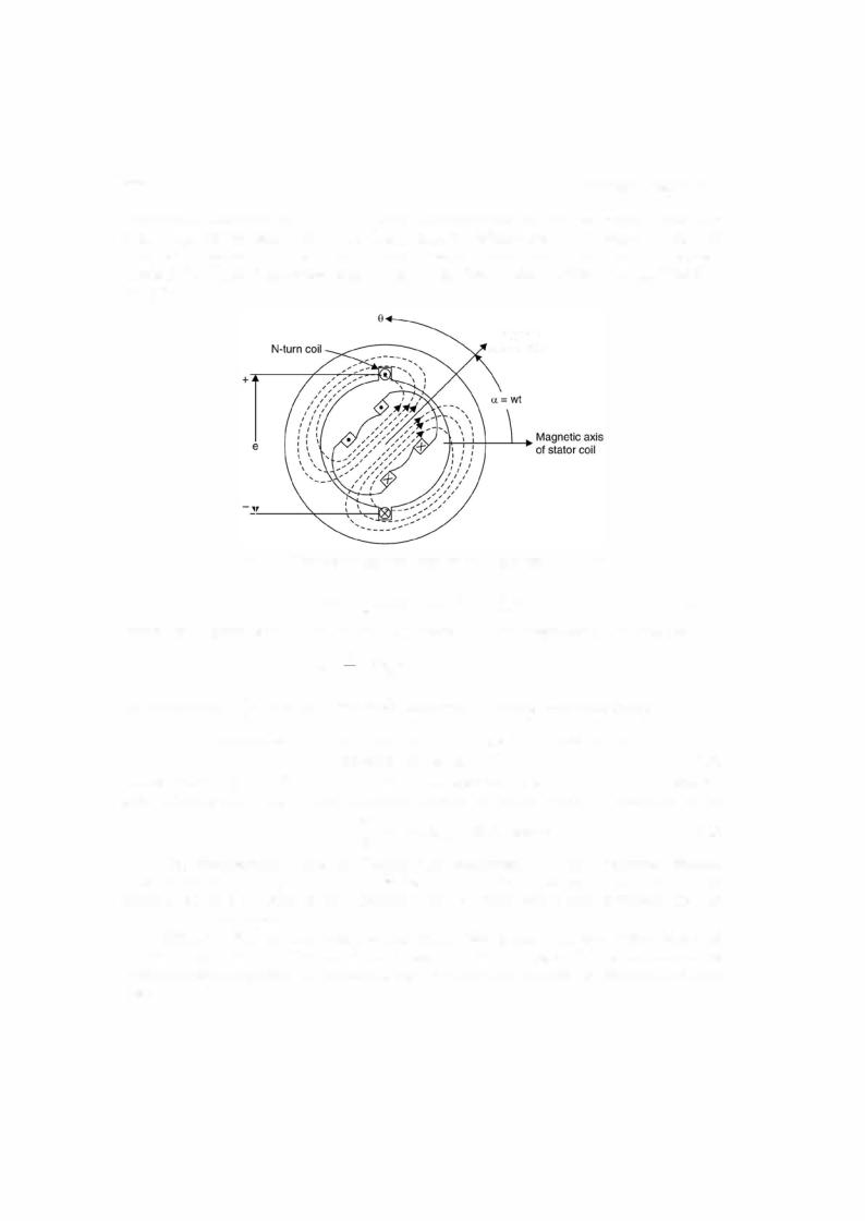
To derive emfequation consider atwopole generator andthe armature windingis a single N-turncoil where coil sides are placed in diametricallyopposite slots onthe inner peripharyofthe slot as shown in Fig. 7.1. The coil spans a full 180 electrical degrees or a complete pole pitch and hence is afullpitch coil. Whenthe rotor magnetic axis coincides withthe stator magnetic axis the flux cut by the coil is maximum as the stator magnetic axis is normal to the plane containing the coil. As rotorrotates through an angle8 in time t from this position anticlockwise, the component ofthe rotorflux along the stator magnetic axis is cosine ofthe angle. Hence the field winding on the rotor produces a sinusoidal space wave (note that the stator coil is fixed in space) of flux

THREE-PHASE SYNCHRONOUS MACHINES |
279 |
e = co N<j> sin |
cot |
...(7.5) |
Hence retaining this term we have |
|
|
Therefore, the peak valueEmof= 2 fN<j> |
|
|
the inducedvoltage is |
|
|
n |
= 4.44fN<j> |
|
or the r.m.s. value ofthe induced voltage is |
...(7.6) |
|
E = J2 fN<j> |
||
21t |
|
|
Eqaution (7.6) is identicalin form to the emfequationofthe transformer. Relative motion ofa coil and a constant magnitude spatial flux density wave in a rotating machine produces the same voltage effect as does a timevaryingflux in associationwithstationarycoilsin a transformer.
Rotation, therefore, introduces the time element and transforms a space distribution of flux density into a time variation ofvoltage.
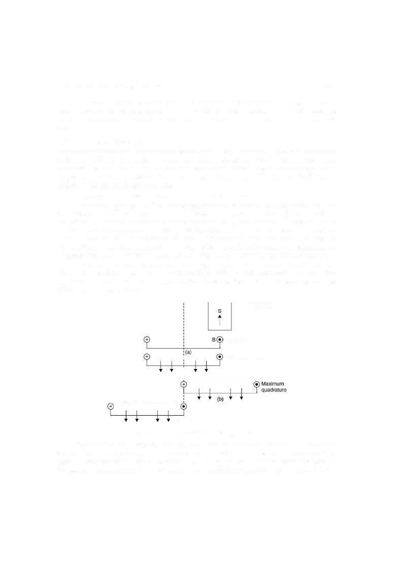
Equation (7.6) indicates thatvoltageinduced is a single phase voltage. Fortheproduction of 3-phase voltages we need three coils displaced 120 electrical degrees in space. Here we have assumedthat the coil spans fullpole pitch that is the two sides ofthe coil are 180° electrical apart and all the turns ofthe coil are concentrated in one pair ofslots. In actual practice the armature coils ofeach phase are distributed in a numberofslots. Whenthe coils comprising a phase ofthe winding are distributed in two or more slots per pole, the emfs in the adjacent coil will be out of phase with respect to oneN another and their resultant will be less than their algebraic sum. In otherwords,whenthe turnsofa concentratedwindingare spreadoutthe resultant emfwillbe less thanwhatis given in equation (7.6) andthefactor (less than unity) by whichthe latterKb must be multiplied in order to obtain the actual emfis called the breadth factor, denoted by and is
given as |
K |
|
|
sin (qy/2) |
|
|
b |
sin y/2 |
=
the adjacent slots and equals 180 |
q |
|
Equation(7.6) is modified as |
E = 4.44 KJ<j>N |
|
|
...(7.7) |
where q is the number of slots for pole per phase andyis the angle in electrical degrees between electrical degrees divided by the number of slots per pole.
A distributed winding makes better use ofthe iron and copper and improves the waveform.
Equation (7.7) presumes that the coils are full pitched i.e., the two sides are 180° electrical degree apart.
Ifthe anglebetweenthe two sides ofthe coilis less than 180 electrical degrees, itis known
as shortpitchedcoil and thevoltage inthe two sides are not same. Thisis also known as chording |
||
of coil. Ifthe chording is say by an angle |
P |
|
the effective voltage will be multiplied by a factor |
||
cos p/2 and is known as pitch factor denoted by K and therefore ifthe windingis distributed and |
||
E = 4.44 KpKb<j> fN |
...(7.8) |
|
equation 7.8 as given here |
|
|
short pitched, equation (7.6) is modifiedtop, |
|
|
The short pitched coils are extensively used for the reason that the waveform is more nearly sinusoidal (Harmonics are eliminated) than with full pitch windings and because ofthe saving in copper and the greater stiffness of the coils due to the shorter end connections. The latterreasonis more importantinthe case oftwo pole high speed turbo alternators because ofthe bending stresses producedinthe end connections under short circuit conditions.


THREE-PHASE SYNCHRONOUS MACHINES |
281 |
a
..:
(C) |
- - - - |
|
|
Axis of |
|
|
|
|
phase |
|
|||
|
|
(d) Simplified 2-pole 3-phase stator winding |
||||
Fig. 7.3. Illustrating the production of a rotatingc |
magnetic |
|||||
|
ib |
|
ic |
,,/ |
pole 3-phase stator winding. |
|
field by means of 3-phase currents. Simplified 2- II |
|
|||||
At this moment the currents |
and |
|
are both I 2I in the negative direction as shown in |
|||
the phasor diagram which is the actual instantaneous direction. The/ corresponding mmfs of phase b and c are shown by the phasers Fb and Fe both equal to Fma 2 drawn in the negative direction ofrespective magnetic axes. The resultant is obtained by taking the phasor sum ofthe
three phasers which comes to Fmaxcentred along the magnetic axis ofphase a.
It represents a sinusoidal space wave with its positive halfwave centred on the axis of
phase a and having an amplitude times that ofthe phase a. 2
Consider the instant t1 such that cot1 = 3,1t as shown in Fig. 7.3 (b) the currents in phase a
and b are a positive half-maximum and that in phase c is a negative maximum as shown in corresponding phasordiagram. The individual mmfcomponents andtheirresultant are shownin Fig. 7.3 (b). Theresultanthas the same magnitude as att = 0 butithas nowrotatedanticlockwise
60° electrical in space. Similarly at mt2 = 21t3 when phase b current is a positive maximum and
the phasea andc currents are anegative halfmaximum (see phasor diagram), the same resultant mmf distribution is obtained but it has rotated another 60° in anticlockwise direction and now it is along magnetic field axis ofphase b. With passage oftime the resultant mmf wave retains its sinusoidalform and amplitudebut shifts progressively around the air gap. This shift corresponds to a field rotating uniformly around the circumference ofthe air gap.
In one cycle the resultant mmfcomes back in the position ofFig. 7.3 (a). The mmfwave, therefore, makes one revolutions per cycle in a 2-pole machine and in one cycle the rotor has moved one complete revolution in a 2-pole machine and hence in a P-pole machine the wave