

Basic_Electrical_Engineering_4th_edition
.pdf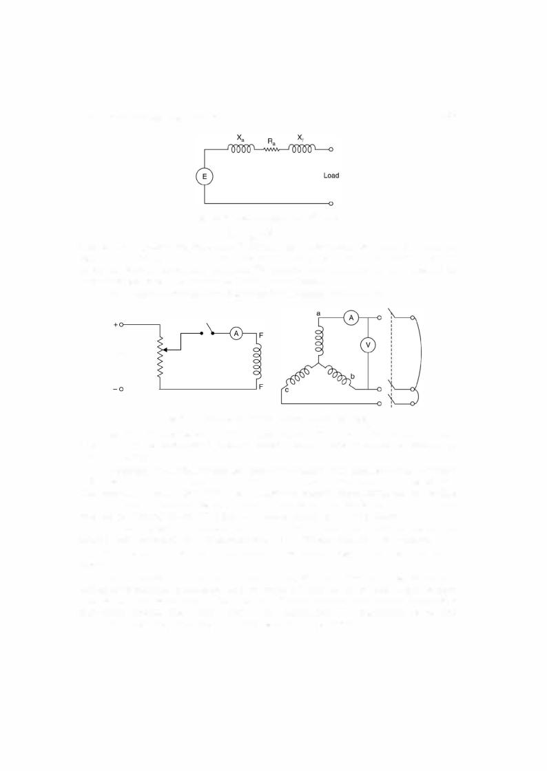
286 |
ELECTRICAL ENGINEERING |
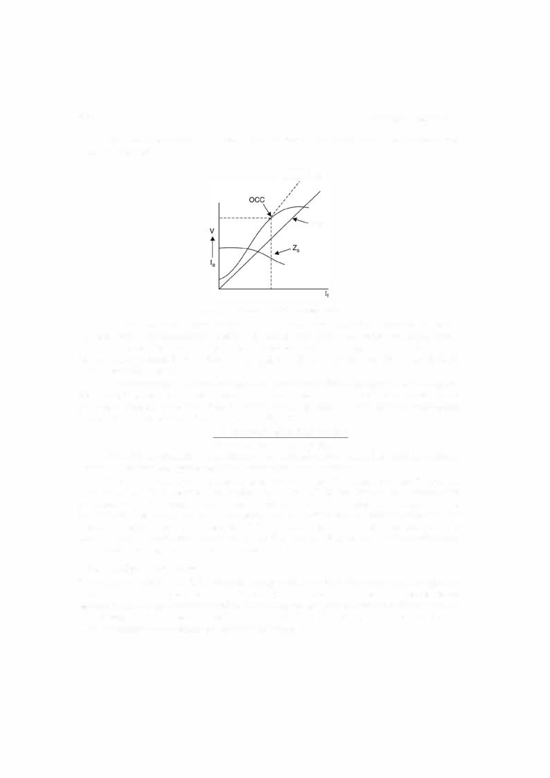
Plot this characteristic on the same sheet where we have drawn the OC characteristic as shown in Fig. 7.8.
Airgap characteristic
sec
Fig. 7.8. OCC and SCC of the alternator.
The open circuit characteristic will usually be moreorless saturation characteristicbeyond the ratedvoltage ofthe alternator because ofsaturation ofthe iron part ofthe magnetic circuit ; but the initial straight part of the curve, if extended yields the air gap characteristic since it represents the relationbetween the voltage (and, therefore, the air gap flux) for the condition of zero reluctance of the iron.
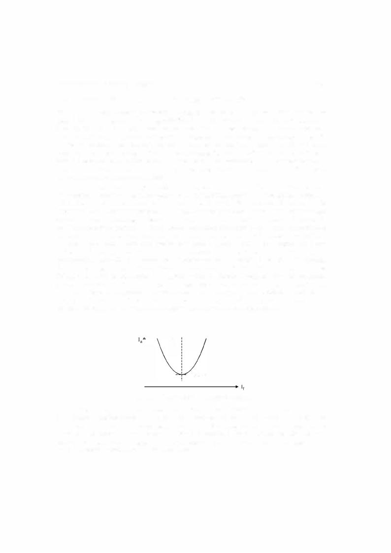
Ifnow thevoltage ordinate corresponding to anyvalue offield excitationis divided bythe short circuit current for the same excitation, the quotient is the synchronous impedance or reactance. Repeating this procedure for several values of excitation the curve of synchronous impedance can be obtained which is shown in Fig. 7.8.
Z8 = OC voltage for some field current SC current for same field current
Ifthe OC characteristic were a straight line the synchronous impedance wouldbe constant. Actually, it is variable, decreasing with increasing values ofexcitation.
Ifthe OC voltage is taken along the straight line ofthe OCC, the synchronous impedance calculated from the current will be too large and if the voltage regulation of the alternator is computedusingthisvalue ofsynchronousimpedance, thecomputedregulationispoorerthan itis in actual practice, thus giving rise to thedesignationpessimistic method. Since the ratedvoltage of the alternator is near the knee of the OCC characteristic, corresponding to that the short circuit current is found from the plot and the ratio ofthe two should be used as the synchronous impedance forvoltage regulation calculations.
7.2.5Voltage Regulation
When an alternatoris loaded, the terminalvoltageofthe alternator changes dependinguponthe magnitude ofload and its power factor. The change in voltage is due to the armature resistance leakagereactanceand armaturereaction. Thevoltage regulationis defined as the riseinterminal voltage expressed in percent ofrated terminal voltage when the load current is reduced to zero, the field excitation and frequencyremainingconstant.

THREE-PHASE SYNCHRONOUS MACHINES |
287 |
Thus
. I E l - I V I % voltage regulat10n =
I V I
The term rise involtage used in thei.eabove., definition assumes that the load is inductive.
However, ifthe load is capacitive the load is supplying lagging vars to the generator and hence the excitationrequiredis reduced and hence I E I is reduced and the terminalvoltage willbe higherwhen the loadis connected as comparedtowhenthe loadis reduced to zero. In such a situationthevoltageregulationis negative.
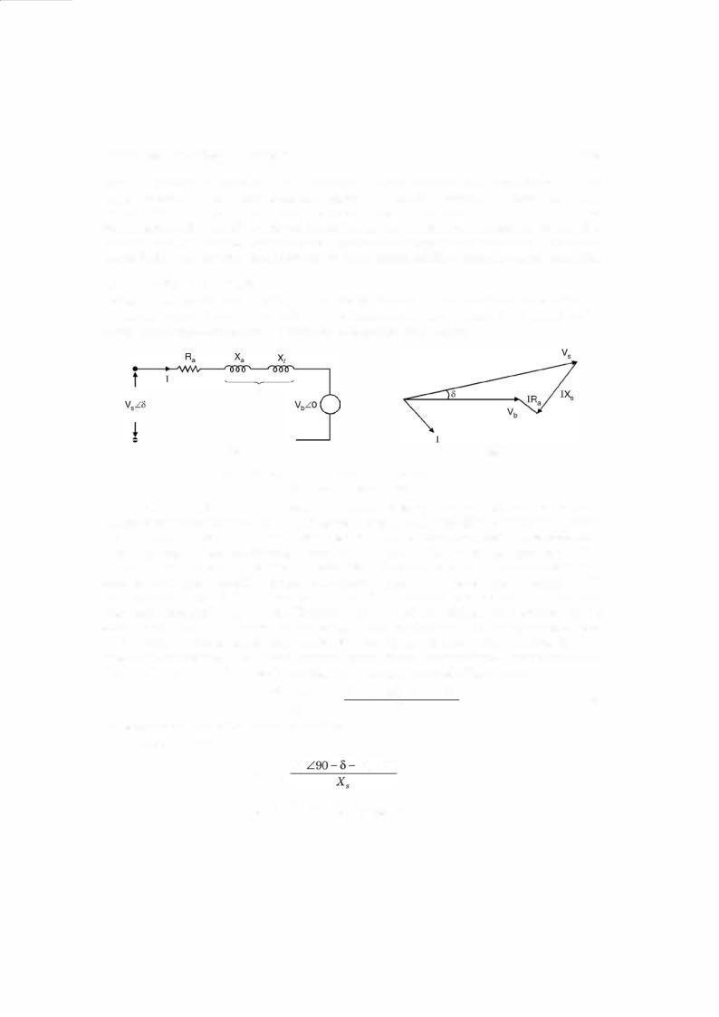
Ifwe compare the equivalentcircuit ofan alternator as shown is Fig. 7.6 with that ofthe approximate equivalentcircuitofatransformer as shownin Fig. 5.13 wefindthatbothrepresent identicalfeatures and are a series combination ofR and X. The physical interpretationofR and X may be different. We draw the phasor diagram for an alternator both for lag and lead p.f. as shown in Fig. 7.9, using ofcourse the equivalent circuit of Fig. 7.6.
E |
E |
|
|
v |
|
|
IR, |
|
v |
(a) |
(b) |
Fig. 7.9. Phasor diagram for an alternator |
(a) lag p.f. (b) lead p.f. |
Here V is the terminal voltage under load condition and E is the induced voltage or the terminal voltage when the load is zero. cos<I> the p.f. ofthe load and 8 is the angle between E and V and is known as torque angle or power angle or load angle.
From the phasor diagram = +
E V IRa +j IX8
where E, V and I are phasor quantities. From here usually V, I, cos <j>, Ra and Xs are known, the magnitude of E can be obtained and hence voltage regulation can be obtained. However, if approximatevalue ofvoltage regulationis required the following expression can be used asis done in case of a transformer.
=IRVa cos < j > ±IXVs sin<j>.
7.2.6Losses and EfficiencyApproximatevoltage regulation
Normally we define efficiency ofa machine as the ratio ofoutput to its input. For a generator it is usually convenient to define efficiency as
Output Output + losses

288 |
ELECTRICAL ENGINEERING |
It is due to the fact that even when all facilities ofmeasurement are available itis difficult to measure mechanical power input to the alternator.
The losses directlychargeable to a synchronous generatorinclude
1. I2R loss in (a) armature winding (b) in field winding (c) at the contact between brushes and slip rings.
2. Core loss.
3. Friction and windage loss including the loss due to circulation of air through a closed ventilating system and also the brush friction loss at the slip rings.
4. The strayloadloss causedby eddycurrentsinthe armature conductors andbyadditional core loss due to the distortion ofthe magnetic field underload conditions.
The I2R losses in the armature and field windings are computed by using the de value of resistance corrected to the working temperature of75°C.
The core loss including hysteresis and eddy current losses, is that which corresponds to zero main flux atratedfrequency when the machine develops anopen circuit (noload) voltage per phase equal to the phasor sum ofits ratedvoltage per phase andthe ohmic drop per phase.
7.2.7Magnetic Poles in Machines
The torque developed by electrical machines is the result of attraction and repulsion between magnetic poles on the rotor and stator. We know that magnetic poles oflike polarity repel each otherwhereas magnetic poles ofunlike polarity attract eachother. Inmachines, the windings are so designed that they develop magnetic poles on the inside surface ofthe stator and the outside surface ofthe rotor. In other words, these poles appear onthe inner and outer surfaces ofthe air gap. Repulsion and attraction between therotor poles and those ofthe stator produce a torque on the rotor and a reaction torque against the stator.
To produce a unidirectional and continuous torque, the no. ofrotor poles must equal the number of stator poles. The no. of poles on either the rotor or the stator must be even. If a machine has four stator poles, there must be fourrotor poles and the machine is said to have four poles. Ifthe machine is in the motor mode, the torque on the rotor causes it to rotate.
Since the rotor poles have constantpolarity, theirwindings must be supplied with direct current. This current may be provided by an external de generator or by a rectifier. In this case the leads from the fieldwinding are connectedto insulated rings mountedconcentrically on the shaft. Stationarycontacts calledbrushes ride on these slip rings to carrycurrent to the rotating fieldwindings from the de supply. The brushes are made ofa carbon compound to provide a good contact with low mechanical friction. An external d.c. generator used to provide field current is called an exciter.
7.2.8 Steady State Operation
As mentioned earlier the synchronous motor as such is not self-starting. This is explained as follows : Supposewefeedde supplytothefieldwindingontherotorthrough an exciter. As aresult northand southpoles are set up ontherotor. These northand southpoles are stationaryin space. Ifwe feed three-phase supply to the statorwinding, this gives rise to arotatingmagneticfieldof constant magnitude and rotating at synchronous speed. The north and south poles ofthe stator magnetic field are rotating at synchronous speed. Suppose at the instant ofswitching, the north

THREE-PHASE SYNCHRONOUS MACHINES |
293 |
field is produced in the air gap which induces currents in the bars which further produces flux. The interactionofthefluxesproduces torqueinthe directionoffieldrotation. In other words, the motor is started as an induction motor, the bars in the pole face slots forming a sort of squirrel cage rotor. Induction motor action will bring the motorto nearly synchronous speed. At synchro nous speed thereis no relative motion between the poles ofthe air gap field andthe pole face bars. No current is induced in the bars at synchronous speed, and no torque would be produced by them. However, the maximum speed developedon induction motor actionisvery close to synchro nous speed and the rotor falls into step when the de field current is switched on.
The field winding terminals are usually shorted through a resistor during starting until such time that the fieldis excited. This has two advantages. First it protects the slip ring insula tionfromthe high acvoltageinducedin thefieldduringstarting. Second the currentcirculating in the field winding would provide a small additional accelerating torque.
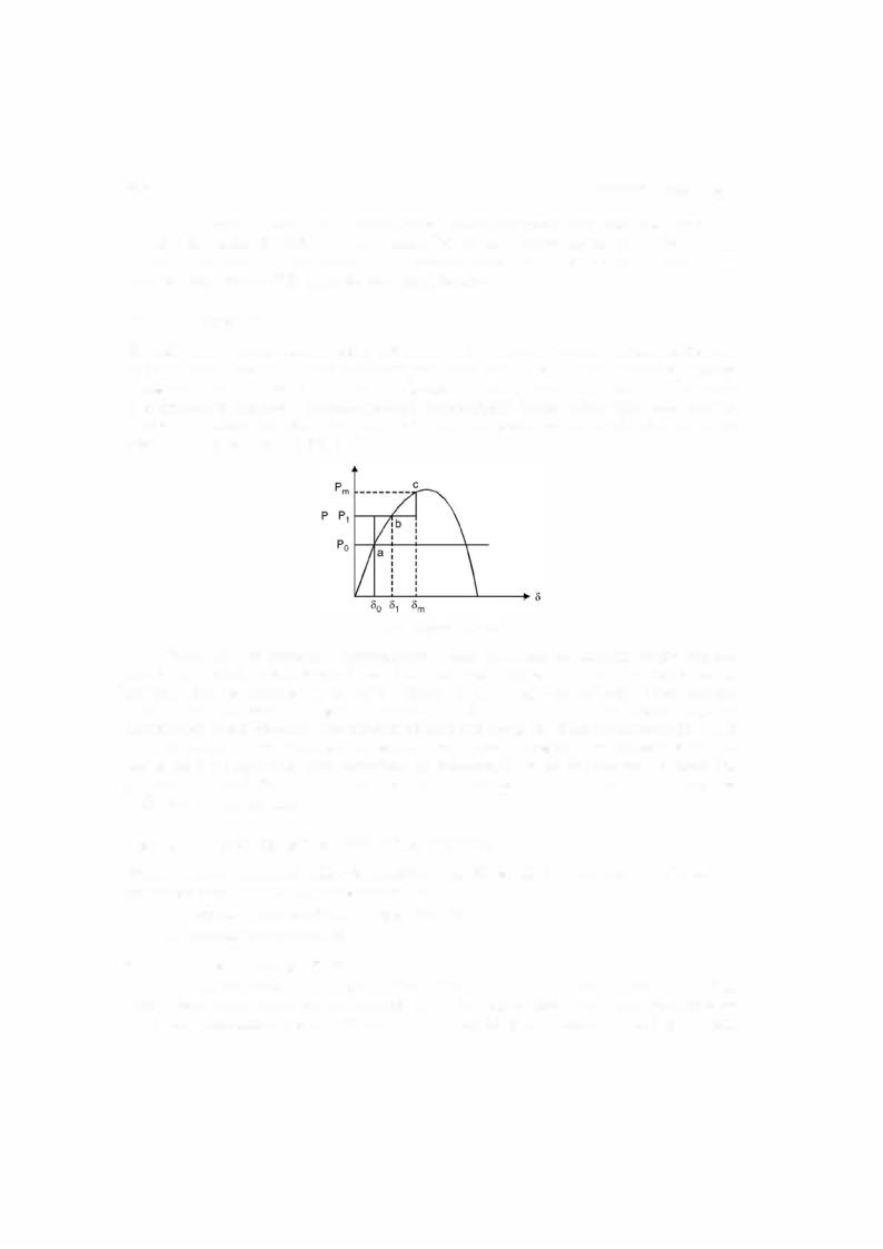
The heavybarwinding inthe pole faces serve an additional purpose. As mentioned inthe previousarticlethatwhenthere is suddenchange ofload the load angle8changes to adjustto the new loadrequirement. The magnetic attractionbetween the air gap flux and the rotor mmfpoles has a springlike quality and the rotor has considerableinertia. As a result there is an oscillatory motionofthe rotor superimposed overthe normal synchronous rotation ofthe shaft. This relative motioniscalledhunting. The relative speed betweenthe air gap flux and thebars induces currents in these bars. The field set up by these currents produces a torque that opposes any change in 8 and the angular oscillation is damped out fast. For this reason the pole face bars are called damper bars and the winding consisting ofthese heavybars and their end connections is called the damper windingorhytheirFrench name, the amortisseurwinding (Roughly translatedthis means "killer winding"). Because ofhighdegreeofhuntingpresentinthesemachines, thedamper windings are installedin nearly all synchronous machines, generators as well as motors having salient poles. Cylindrical rotor cores cannot be laminated and still maintain the required mechanical strength. Eddy currents, therefore, can circulate freely in the pole faces. Since the flux through the pole faces remains constant under steady state condition, these eddy currents are induced only during transients (e.g. during change of load). The interaction of the eddy currents with the air gap flux provides the necessary damping action in cylindrical rotor synchronous machines.
7.5.2Auxiliary Motor Starting
The auxiliary motormaybe a de shunt motor oran induction motor havingthe same no. ofpoles as the synchronous motor or two poles less as compared to synchronous motor. The job of the auxiliary motor is to bring the synchronous motor to synchronous speed or near synchronous speed. The auxiliary motor is mechanically coupled to the synchronous motor. No load is put on the synchronous motor during starting. Therefore, the auxiliary motor has to overcome only the inertia ofthe synchronous motor and mayhave its rating much smaller than that ofthe synchro nous motor being started.
Whenthe speedis near synchronous speed, the 3-phase supplyis switched onto the arma ture and de supply to the field circuit of synchronous motor. The synchronous motor pulls into step, its speed rises to synchronous speed and it continues to run at this speed.
If the induction motor has two poles less than synchronous motor, the induction motor speed is higher than the synchronous speed ofthe synchronous motor. Once the higher speed is