

Basic_Electrical_Engineering_4th_edition
.pdf
BASIC INSTRUMENTS |
1 95 |
esh' Now <l>se is in phase disc which lags behind
Let
or
and
and
with the current which produces it and ese is the induced voltage in the <l>se by 90° and again assuming disc to be resistive ise is in phase with ese·
V = Vm sin wt |
|
I = Im sin (mt - < ))> |
|||||
<l>se oc Im sin (rot - <)>) |
J |
|
|
||||
V o c_ |
d<l>sh |
or <l>sh = - |
m |
sin mt dt |
|||
dt |
V |
||||||
<)>sh = |
|
vm |
|
|
|
|
|
- - cos rot |
|
|
|||||
esh oc |
|
m |
w sin rot |
|
|
||
d<!>sh = V |
|
|
|
||||
|
|
dt |
|
|
|
|
|
oc |
vmCOsin rot |
|
|
|
|
||
ish oc |
Vm sin CO |
|
|
|
|
||
|
|
rot |
|
|
|
|
|
Similarly
and
ese oc
ise oc
d |
|
Im co |
e)>s |
||
dt |
e oc |
|
Im co COS (rot
cos - <j)l
(rot-
<)>)
The net torque
is
= |
<l> |
c |
i |
s |
h - |
h |
|
|
|
|
|
|
|
s |
|
|
<!>s ise |
<!>) v |
|
w |
|
|
<!>) |
||
|
D |
|
Im sin (rot - |
m sin rot+ |
|
cos (rot - |
||||||
T |
oc |
|
vm cos mt Im |
|
|
|||||||
|
|
|
VI cos <)> |
|
|
|
|
|
|
|||
|
|
|
|
|
mim[sin (rot - <)>) sin mt + cos mt cos (rot -co |
|
|
|||||
|
|
oc V |
|
|
|
|
<)>)] |
|
||||
oc Vm.Im. cos (rot - <)> - mt)
TD oc Vmim COS <)> oc
oc the power in the circuit.
Sincethe deflectingtorque is proportionalto thepowerinthecircuitand the instrument is springcontrolledthe scale is uniform. Similarlyfor dynamometertype wattmeter also the scale is uniform
Compared with dynamometer type wattmeters, the induction wattmeter have the advan tage of a greater working torque and length of scale. However, they suffer from the inherent disadvantages ofless accuracy greaterweightofmoving system, greater power consumption and also that these can be used only on ac circuits.
4.6METHOD OF CONNECTION IN THE CIRCUIT
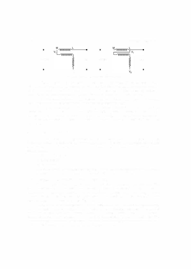
There are two ways in which a wattmeter could be connected in a circuit as shown in Fig.
4.13.There are fourterminals in a wattmeter. Across terminalsML is the currentcoil and across
V1V2 is the pressure coil. M standsforthe mains (supply) side ofthe currentcoil and L stands for the load side ofthe current coil. Ifconnections ofany one coil is made opposite towhatis shownin Fig. 4.13, the meterwouldgive deflectionin the opposite direction and hence the connection ofany one ofthe coils should be reversed to obtain positive deflection. Even though the two connections
shown above are normal, neither measures the power in the load accurately.


1 98 |
|
|
|
|
|
|
|
|
|
|
ELECTRICAL ENGINEERING |
|
Using the theory ofinduction wattmeter. |
|
|
|
|
||||||
|
Operating or drivingtorque |
oc |
VI cos <P |
TD |
|
|
|
||||
|
equal to T13 , we have |
|
N o cVI cos qi |
|
|
|
|||||
where Vis the supplyvoltage across the shunt coil and!the load current through the series coil |
|||||||||||
ofthe meter and <P the p.f. angle between Vand I. |
|
|
|
|
|||||||
|
Now the braking torque has been shown to be proportional to the speed N ofthe disc i.e. |
||||||||||
|
|
|
|
TB |
|
N |
|
is |
|
|
|
|
Since for a steady speedN, the driving torque |
|
|
|
|||||||
or |
power is proportional to speed N |
which equals |
N dt |
is proportional to |
|||||||
|
Thus the total no. ofrevolutions |
||||||||||
|
|
oc |
|
|
|||||||
|
fVI cos c)> dt |
i.e. proportional to energyf |
supplied. |
||||||||
The speedofthe disccanbeadjustedby suitably positioningthebrake magnetwithrespect to the spindle ofthe disc. Ifthe brake magnet is moved towards the spindle the braking torque decreases and iftaken away from the spindle the braking torque increases.
An energymeterisratedinterms ofthe supply voltage, the full load current and number of revolutions of the disc per kWhr (also known as constant of the energy meter). These are marked on the dial ofthe energy meter.
4.7.2Creep
In some meters a slow but continuous rotation ofthe disc is obtained when the pressure coils are energized and there is no load current passing through the current coil i.e. current coil is not energized. This may be due to incorrect friction compensation to vibration, to stray mag netic field or to the fact thatthe supply voltage is in excess ofthe normal voltage.
Toprevent suchcreepingofthe metertwoholes or slots are cut inthe discon opposite sides ofthe spindle. The disc tends to remain stationary when one ofthe holes comes under one ofthe poles ofthe shunt magnet. In some cases a small piece ofiron wire is attached to the edge ofthe disc. The force of attraction ofthe brake magnet upon this iron wire is sufficient to prevent the creeping ofthe disc under no load condition.
4.7.3Friction Compensation
The two shading bands embrace the flux contained in the two outer limbs ofthe shunt magnet and thus eddy currents are induced in them which cause a phase displacement between the enclosedfluxandthe main gapflux.As a result a small drivingtorque is exerted on the disc, this torque being adjusted by variation ofthe position ofthese bands to compensate for friction torque in the instrument.
The friction compensation can be checked whether it is correct or not by connecting light load under which condition it should run at the correct speed.

BASIC INSTRUMENTS |
1 99 |
4.7.4Meter Phase Angle Error
It is desiredthatthe phase angle between the applied voltage to the pressure coil and the shuntmagnetfluxshouldbe at 90° whichisadjustedwiththehelp ofshadingband onthe shunt magnet. An error due to incorrect adjustment ofthe positionofthis shading band will be evident when the meter is tested on a load whose p.f. is less than unity. An error on the "fast" side under these conditions can he eliminated hy bringing the shading hand further drawn the limb ofthe shunt magnet i.e. nearer to the disc.
Example 4.6. For 20 A, 230 V meter the constant is 480 revolutions |
|
Whr. If upon test |
|||
for a load of 4.6 kW the disc makes 40 revolutions in 66 sec. Calculate the |
error. |
||||
|
II? |
|
|||
Solution. In 66 sec. the energy consumedby the load is 4.6 x 3600 kWhr = 0.0843 kWhr |
|||||
The energy recorded by the meter |
40 = 0.0833 kwhr |
|
|
|
|
|
|
480 |
|
|
|
Hence the meter is moving slow |
and it is slow by |
|
|
|
|
|
-- |
|
|
|
|
0.0843 - 0.0833 x 100
0.0843
=0.0843O.OOl x 100 :::::1.2 percent slow.
4.8POLYPHASE INDUCTION WATT HOUR METERS
As in the case ofpower measurement with a two-element wattmeter, the energy supplied
to a three phase circuit can be measured by a two element ofthe induction type, each element being similar to the construction to the single element meter.
There are two discs mounted on the same spindle and two separate brake magnets. The spindle drives a single counting train. In addition to the phase adjustment and friction error compensation in each element, one ofthe elements has an adjustable magnetic shunt across its shunt magnet, in order that the driving torque for the same watts may be the same in the two instruments. Incarrying out this adjustment, the two current coils ofthe meter are connectedin series andthe two pressurecoils inparallel, the polaritiesbeing suchthatthe two drivingtorques are in opposition. Adjustment ofthe magnetic shuntis carriedout untilthe meterceases to rotate with full rated watts supplied to both elements.
The adjustmentsforphase displacement, friction compensation andforthe correctposition of the brake magnet are made upon the two elements separately, a single phase circuit being used. The adjustment of the brake magnet positions must be carried out on the two elements alternately, since both magnets are operative in producing the braking torque. Both the shunt elements shouldbeenergizedmeanwhile, to allowforinteraction.
The connections to these polyphase meters are the same as those employed in the two wattmeter method ofmeasuringthree phase power.
Example 4.7. A dynamometer wattmeter with its voltage coil connected across the load side of the instrument reads 250 W If the load voltage be 200 V. What power is being taken by the load ? The voltage coil has a resistance of 2000 ohm.

200 |
ELECTRICAL ENGINEERING |
Solution. The connections are as shown
Load 200 v
2000 Q
Fig. E4.7
Powertaken by theload = Power recordedby the wattmeter-power consumed inthe pres sure coil.
The current through the pressure coil is
2000200 = 0.1 A
and sincethepressurecoilishighly non-inductive, power absorbedbythepressure coil is VI = 200 x 0.1 = 20 watts. Hence power taken by the load is 250 - 20 = 230 watts.
Example 4.8. A 50 A, 230 V meter on full load test makes 61 revolution in 37 sec. If the normal disc speed is 520 revolutions per kWhr. What is the percentage error ?
Solution. The full load is 230 x 50 |
|
1 1.500 kW |
|
|
|
||
In 37 secs the energy supplied |
= 1 1.5 x |
3600 |
= |
0.11819 kwhr |
|||
|
= |
61 |
|
|
|
||
The energyrecorded bythe meter |
= |
= 0.1173 |
|
|
|||
|
|
520 |
|
|
|
|
|
This means the disc or the meter is slow |
|
|
|
|
|
||
|
|
0.11819 - 0. 1173 |
|
||||
The percentage error |
= - |
0.1 1819 |
|
|
x 100 |
||
=0.75% slow Ans.
4.9PHANTOM OR FICTITIOUS LOAD
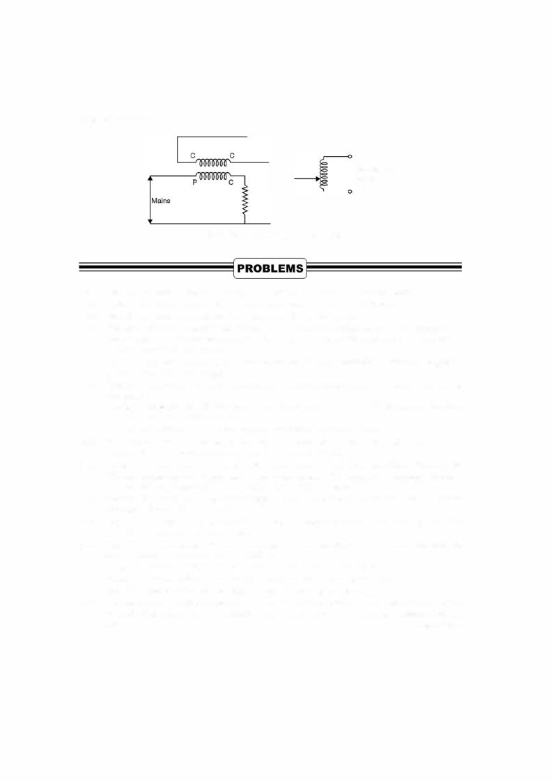
When the capacity ofa meterundertest is high, a test with the ordinary or actual loading
wouldinvolve aconsiderablewaste ofpower. Toavoidthis, phantom orfictitiousloading arrange ment is employed. Inthis, voltage across the pressure coil correspondtothe ratedvoltage whereas the currentcoil is suppliedfrom a separate lowvoltage source Fig. 4.15. This meansthat thetotal power supplied for the test is that due to the small pressure coil current at normal voltage plus that due to the load current at a lowvoltage and thus the total power supplied is only a compara tively small amount.
Ifa high capacity meter is to be listed whilstin service, the pressure coil is supplied from the line in the normal way but the current coil is removed from the consumer's load circuit and replaced by a short circuiting connection. The current coil is then supplied from a low voltage source for purposes oftesting.
BASIC INSTRUMENTS |
201 |
Low voltage supply
Fig. 4.15. Phantom loading of energy meter.
4.1.
4.2.Descrihe the c n tru t n and pr cip e perat o a m v g ga van ter.
4.3.Explain clearly how a galvanometer can be used as an ammeter or a voltmeter.
4.4.Explain the basic requirements of an instrument for measurement.
4.5.Explain clearly why a movingcoil instrument can be used on de only and not on a.c. circuits. Explain whythe resistance of an ammeter should be as low as possible where as that ofvoltmeter
4.6.it should be as high as possible.
Explain how an ammeter and a voltmeter are connected in anelectriccircuit. What will happen ifin o in coil lo s c io omel ofo i n of
4.7. their positions are interchanged ?
Explain with neat diagrams the construction principle of operation and application of a moving
4.8.iron ammeter.
Develop expressions for deflecting torque and control torque for a PMMC instrument and show
4.9.that the scale of the instrument is linear.
4.10.Differentiate between a PMMC and dynamometer type moving coil instrument.
What do you mean by polarised and non-polarised instrument ? Classify the instrument : PMMC
4.11. dynamometer moving coil. Attraction type MI, repulsion type MI.
4.12.Name which instrument can be used onac only, on d.c. only, and onac and de both. Give reasons. What are induction type ofinstruments ? Show that the deflectingtorque in an induction disc type
4.13.instrument is maximum when the two fluxes are 90° phase apart.
Describe the construction, principle of operation and application of an induction disc type of an
4.14.ammeter. Discuss about its scale.
Explain with diagram the construction, principle of operation and application of (a) Induction
4.15.type (b) dynamometer type wattmeters.
Explain why the potential coil of a dynamometer wattmeter should be highly non-inductive and
4.16.that of induction wattmeter highly inductive.
4.17.What is meant by creeping of an energy meter ? How is this taken care of?
4.18.What is phantom loading ? With a neat diagram explain how it is carried out.
4.19.Explain the construction and principle of operation of a 3-phase energy meter. Q.
The resistance ofa meter movement that has a full scale deflection of 1 mA is 50 Calculate the
value ofthe shunt required to convert the movement to an ammeter having a full scale deflection |
|
of 2 A. |
[Ans. 25 mQ.] |


CHAPTER
5Transformer
5.1INTRODUCTION
A transformer even though is not an energy conversion device, it forms a very important
component ofthe energyconversion system. It is almost an indispensable component inboththe electric and electronic systems. Atransformer transforms electric energyfrom a certain voltage and current levels to another voltage and current levels keeping the frequency ofthe supply the same. Itis because ofthe availabilityofthe transformer that itis possible to generate energyfrom where it is available in abundance far away from the loadcentre and the energy so generated at economic voltage levels can be transmitted at economicvoltagelevels usingtransformers and the same energy can be utilised at economic and safe voltage levels as required by the devices using the electric energy. Theimportance oftransformerinelectric energy system can be gauged bythe fact that a generation of 1 MW requires transformers of3 to 3.5 MVAcapacity from power plant to the consumer points.
The transformer is also very widely used in electroniccircuits i.e. low power low current electronic and control circuits for performing such functions as matching the impedance of a source and the load for maximum power transfer. Atransformer has normally two windings, the primary and the secondary. The primary is one where the source is connected and across the secondary load is connected. If the secondary voltage is higher than the primary voltage it is known as step-up transformer and it is known as step down ifthe secondary voltage is smaller than the primary voltage. However, if the two voltages are equal, it is known as an isolation transform. The one-to-one transformers are used whenit is necessaryor desirable toinsulatethe secondary side ofthecircuitfrom the primarycircuit ; forthoughboth thecircuits willthenhave the same difference ofpotentialbetweentheirterminals, theywill not necessarily have the same difference ofpotentialtoground. Itis tobenotedthat eitherofthetwowindings canbeconsideredas primarywhiletheotherthenservesasthe secondary. Theprimaryisthereforedefinedasone which receives energy from the supply and the secondary as the one which delivers energy to the load. In general, however, the windings are designated aslowtension (LT) or hightension (HT) windings.
In its simplest form the transformer consists of the insulated windings wound on a ferromagnetic core and so disposed with respect to each other as shownin Fig. 5.1 that a current through one ofthe windings will set up a magnetic fluxlinking more or less completely with the turns ofthe other. According to Faraday's laws ofelectromagneticinduction an emfis inducedin the secondarywhichis proportionaltothenumberofturns ofthe secondaryandthefluxlinkingthe secondary. However, the frequencyofthe secondary voltage is same as that ofthe source.
203